
Paxman Heavy Duty Diesel Engines
Types VZ, VX, VY and VYL - 1931 onwards
The Company's First Monobloc Engine
Although Paxman's earliest compression-ignition engines were not introduced until 1927, by late 1930 the Company was preparing to launch what might be described as its next generation of diesels. This was Paxman's first monobloc type, known as the Heavy Duty Diesel Engine. One of the earliest ordered, under Order No 17703 dated 9th December 1930, was a six cylinder VX for the British Industries Fair, Birmingham where it was to be exhibited the following February.
Construction and Main Features
 As explained on the page Heavy-Fuel-Oil Engines, Paxman's first generation of compression-ignition engines were constructed with separate 'A' frames, each supporting a single cylinder. Like its predecessor, the new monobloc engine was a four stroke design with a bedplate carrying the main bearings and crankshaft, surmounted by separate 'A' frames which formed the crank chamber. The key distinguishing feature of the new engine was its single cast-iron cylinder block (monobloc) which housed all the cylinder liners and was carried on top of the 'A' frames. This block was tied to the lower part of the bedplate by long high-tensile bolts which passed through the block and the 'A' frames to the bedplate. The bolts were tightened up to a degree greater than the tension which could be imposed on them by the firing loads of the engine so that they absorbed the whole working load. In its publicity literature Paxman explained that with this method of construction the cast-iron framing was always in compression and not in tension. The resultant greater rigidity of the framework made it possible to keep the crank chamber inspection doors very large without detracting from the strength of the structure.
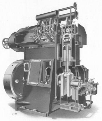
Cut-away illustration of a twin camshaft type of Paxman Heavy Duty Diesel Engine. One of the long through bolts is visible just to the right of the opening in the crankcase.
The earlier Heavy-Fuel-Oil engines were originally 'open' types with relatively basic forms of lubrication even for their main bearings. In 1929 the Company had introduced, as an option across its standard Heavy-Fuel-Oil engine range, enclosed types with forced flow lubrication. The new monobloc engines were designed from the start as fully enclosed and pressure lubricated throughout. All moving parts except the flywheel were enclosed, thus preventing the ingress of dust or moisture which could cause wear. More importantly, total enclosure allowed the use of full pressure lubrication not only for the main and connecting-rod bearings but also for camshaft bearings and valve gear. Lubrication of the camshaft and valve gear was effected by a secondary pressure lubrication system delivering clean oil which was drawn from and returned to the camshaft trays. These innovations made it possible to run the new engines for long periods unattended, and at higher speeds. They also assisted in reducing wear on moving parts to a minimum and maintaining a cleaner operating environment.
Other Technical Details
Valve Gear: For ease of maintenance inlet and exhaust valves were carried in separate cages incorporating removable valve seats. The cages were bolted to cylinder heads and by undoing a few bolts could quickly be removed without disturbing any other components. Spare cages, with valves ground in and ready for use, could be installed in a few minutes, leaving regrinding of the removed valves to be done later when convenient. The valves themselves were operated by rockers carried in the cages, one end of each rocker having a roller cam follower bearing on the camshaft.
On VZ and VX types the valves were arranged horizontally, one in each side of the cylinder head. The VY and VYL types had their valves positioned vertically and fitted in the top of the head.
Camshafts: Types VZ and VX were fitted with twin camshafts, placed on top of the cylinders, one on each side of the engine, operating the inlet and exhaust valves by single rockers. Types VY and VYL had a single camshaft which operated the valves by means of rocking levers.
The camshaft drive was arranged at the flywheel end of the engine, using a roller chain driven from a sprocket on the crankshaft. On types VZ and VX the drive was to a lay shaft and thence through spur gears to the two camshafts. On VY and VYL types the chain drive was taken direct to a sprocket carried on the camshaft.
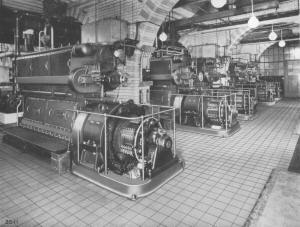
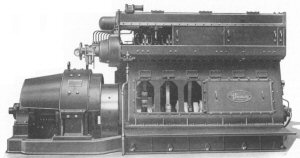 Accessibility: Throughout its history, going back to early steam days, Paxman has always paid careful attention to the issue of accessibility for maintenance and repair. Although the Heavy Duty Diesel was fully enclosed, ease of access was a feature kept clearly in mind at the design stage. The photograph here shows a six cylinder engine with the covers partly removed. Large easily removable crankcase doors gave good access to main bearings and big end bearings. They were also of a sufficient size to allow pistons and connecting rods to be removed through them, without disturbing cylinder heads. The sliding covers on the upper part of the engine gave access to camshafts and valve gear for inspection and servicing whilst preventing the ingress of dirt and escape of lubricating oil.
Fuel Injection: It is clear from contemporary literature that when the VX engine was introduced it was fitted with the spring injection fuel system like its predecessor (1). Also, in a paper he delivered in late 1931 on diesel rail traction, Edward Paxman referred to the fact that many manufacturers had adopted Bosch type pumps but specifically mentioned that his Company had used spring injection for the engine recently fitted in an experimental locomotive (a reference to the LMS Railway's No 1831).
Spring injection worked very successfully with the slower Heavy-Fuel-Oil engines but did not perform ideally at the higher speeds of the new engines. Not long after the Heavy Duty Diesel Engine was introduced its spring injection was replaced with the fuel injection system brought out by Bosch in 1927. After this change VZ and VX types were fitted with a Bosch-type monobloc fuel pump driven from an extension of one of the main camshafts. VY and VYL types were fitted with separate fuel pumps mounted adjacent to each cylinder and driven direct from the main camshaft.
A fuller specification of the Paxman Heavy Duty Diesel Engine, as found in Paxman Publication 1022, in reproduced in Appendix A below
Welded Steel Frame Engines
The introduction of Paxman's new monobloc engine in 1931 was not the only major landmark in the development of the Company's diesel engines that year. As an alternative to the cast-iron through bolt construction of the new engine in its standard form, a fabricated steel frame version was also brought out. Paxman was the first firm in Britain to construct diesel engines with entirely welded steel framework and showed what was probably the first of this type at the Shipping, Engineering and Machinery Exhibition at Olympia in September 1931. On display was a six cylinder VXS, developing 300 bhp at 600 rpm, direct coupled to a 200 kW DC generator. The engine was run at the exhibition to demonstrate the smoothness of operation and freedom from vibration. However, the outstanding feature, as reported in technical journals at the time, was its welded steel frame (2).
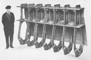 The design of the frame was the subject of patents (3) taken out by Mr C H Stevens of the Steel Barrel Co Ltd, Uxbridge which built the frame for the engine exhibited at Olympia. Paxman subsequently used this method of construction under licence from Mr Stevens. The frame was designed so that all the firing stresses were taken direct from the cylinder head right down to the seating of the crankshaft bearings in continuous steel plates or slings, without any load being imposed on the welding. As shown in the photograph here, the vertical plates or slings were held together by two suitably slotted horizontal plates which were worked into position and welded to them. The top plate acted as a seating for the cylinder heads while the lower plate served as a housing for the cylinder liners. The simplicity of the construction allowed access to all parts of the framework, making it possible to achieve good quality welds throughout the whole structure.
The advantage of welded steel frame construction was a major reduction in engine weight combined with great strength. The weight of the framework itself was less than half that of the equivalent cast-iron through bolt construction used in Paxman's standard Heavy Duty Diesel Engine. The lighter weight and robustness of the steel framed version were important considerations for portable and semi-portable applications. Substantially reducing the engine's weight while retaining the same power output, enhanced its suitability and attractiveness for rail traction and certain marine applications. Already we are seeing signs of Paxman's constant quest to increase the power to weight ratio of its engines. Records suggest that only six of these steel framed Heavy Duty Diesels were built, two for installation in the LMS Railway's first diesel locomotives and four for auxiliaries in naval ships. Nevertheless it may be argued that these contracts were significant in shaping the future direction of the Company. The high power to weight ratio of its engines led to rail traction and naval applications becoming two of Paxman's most valuable markets throughout the second half of the 20th century. It is interesting to note that the Ventura engine, launched in 1960, had a fabricated steel crankcase and that up to the late 1990s some Valentas built for the Royal Navy also had fabricated crankcases because of their lighter weight and greater shock resistance.
The letter 'S' was added to the engine mark of the steel framed versions of the Heavy Duty Diesel Engine (e.g. VXS and VZS) to differentiate them from the cast-iron ones.
Cylinders, Power Outputs, Speeds and Dimensions
The earliest catalogue we have seen for these Heavy Duty Diesel Engines is No 1022. It bears no date but the introduction reproduces a press cutting of 21st June 1933 so is no earlier than this date. It was possibly prepared to be available in time for the Shipping Exhibition in September that year where the Company exhibited a 4MZ (marine version of the VZ) engine. The types, power outputs and speeds of engines offered in catalogue 1022 are as shown in the table below. Cylinder dimensions are not given in the catalogue; those shown below are taken from a data sheet found in Paxman's Service Department.
| Type | Number of Cylinders | BHP per cylinder | Speed (RPM) cont duty | Bore & Stroke | |
|---|---|---|---|---|---|
| Normal Load | Max Overload for 1 hr | ||||
| VW | 2, 3, 4, 5, 6, 7, 8 | 17.5 | 19.25 | 1,000 | |
| VZ | 2, 3, 4, 5, 6, 7, 8 | 25 | 27.5 | 750 | 6½" x 10" |
| VX | 2, 3, 4, 5, 6, 7, 8 | 50 | 55 | 600 | 9" or 9½" x 12" |
| VY | 3, 4, 5, 6, 7, 8, 9, 10 | 100 | 110 | 500 | 13" x 16" |
| VYL | 3, 4, 5, 6, 7, 8, 9, 10 | 100 | 110 | 330 | 13" x ??" |
Speeds of the S (steel frame) types could be increased by 25% of the above.
The VYL had a lengthened piston stroke to maintain the same power output as the VY but at the lower speed where the customer required a slower running engine.
A later catalogue, No 1042, offers the same types and sizes of engines as those shown in the table above except that there is no reference to the Type VW and the smallest VZ offered is now a 3 cylinder version. It is fair to assume the Type VW had been withdrawn and there is no evidence to suggest that any were ever built. Catalogue No 1042 refers to the diesel-electric paddle boats built for Queensferry so cannot be earlier than 1934.
The VY and VYL Series engines were still be advertised as late as January 1938, then being offered in 5 to 8 cylinder forms, developing 600/1,000 bhp at 333/500 rpm (4). Surviving records suggest that only three VY engines were built, one VYL and two MY.
Types MZ, MZS, MX and MY were marine versions of the VZ, VZS, VX and VY respectively.
Applications and Main Markets
Power Generation
 Like the earlier Heavy-Fuel-Oil Engines, one of the most important applications of the Heavy Duty Diesel Engine range was electrical power generation. Engines were sold to a variety of industrial and commercial concerns for this purpose but scarcely a handful to local authorities.
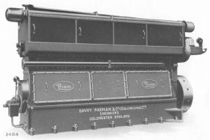
Right - An 8 cylinder VX similar to those supplied for the Bank of England.
Within a few months of the new engine being launched, major orders were received for two prestigious London projects. These were placed by a noted firm of electrical contractors, Drake & Gorham Ltd, on behalf of their clients. The first batch of orders, placed on 22nd June 1931, was for four 8 cylinder 450 bhp VX engines for the Bank of England. The engines, Nos 23830 to 23833 inclusive, were delivered between 19th December 1931 and 16th January 1932.
 The second batch of orders was placed by Drake & Gorham just a few weeks later, in September, for another well-known financial institution. This was for five 6 cylinder 300 bhp VX engines for installation at the Prudential Assurance Company's Head Office at Holborn Bars in which more than 5,000 people were employed. The engines, Nos 23881 to 23885 inclusive, were delivered during the summer of 1932.
Left - This photograph showing the five 6VX engines installed at the Prudential Assurance Co's Head Office appeared in Paxman's Heavy Duty Diesel Engine catalogues.
Marine Auxiliaries
Paxman did not have the success it appears to have hoped for in selling its Heavy-Fuel-Oil Engines into the marine auxiliary market. It fared considerably better in selling its Heavy Duty Diesels for on-board power generation; a market which from then on grew to be a major one for the business.
 Two Portuguese naval vessels, "Gonçalo Velho" and "Gonçalves Zarco", built in 1932/3 were each fitted with a 3MZ auxiliary. Four Royal Navy Halcyon Class minesweepers built in 1934, "HMS Halcyon", "Skipjack", "Harrier" and "Hussar", were each equipped with a steel-framed 3MZS auxiliary.
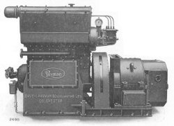
Right - 3 cylinder Heavy Duty Diesel Engine direct coupled to a generator for marine auxiliary purposes.
Auxiliaries were also supplied for passenger ferries and coastal traders. For four of the latter owned by Coast Lines Ltd, "British Coast" (1933), "Atlantic Coast" (1934), "Pacific Coast" (1935) and "Ocean Coast" (c.1936), no less than ten MZ engines were ordered. These comprised eight 4MZ and two 3MZ engines, driving Campbell & Isherwood 220 volt DC generators at 750 rpm, with outputs of 60kW and 45kW respectively. It is interesting to note that Coast Lines Ltd had a large shareholding in David MacBrayne so perhaps it was Paxman's earlier dealings with MacBrayne over "DEV Lochfyne" which provided the entrée to the Coast Lines business.
Diesel-Electric Marine Propulsion
 This application is essentially a specialised form of electrical power generation. Two of Paxman's earlier Heavy-Fuel-Oil Engines had been supplied as the prime movers for what is believed to have been the first diesel-electric vessel to operate in British coastal waters, MacBrayne's "DEV Lochfyne". Building on that pioneering step Paxman Heavy Duty Diesels were supplied as prime movers for at least five diesel-electric vessels constructed during the 1930s.
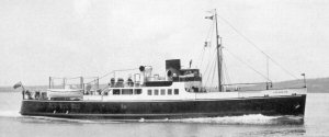
Right: David MacBrayne's "MV Lochnevis".
One of these was another MacBrayne ship, "MV Lochnevis", built by William Denny & Brothers Ltd of Dumbarton in 1934 and powered by two 6 cylinder MY engines, rated at 650 bhp each. To minimise vibration being transmitted to the hull, the engines and generators were mounted on specially designed bedplates which incorporated springs. This innovative feature was further developed on a later Paxman-engined MacBrayne ship, "Lochiel".
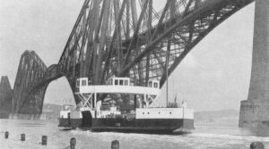 Also built by William Denny in 1933/34 were two paddle wheel driven ferries, "Queen Margaret" and "Robert the Bruce", for the Firth of Forth crossing at Queensferry, north of Edinburgh. The first diesel-electric paddle ferries to be constructed for service in the British Isles, each was fitted with two 8 cylinder MZ engines with individual ratings of 175/192½ bhp at 750 rpm. Paxman records suggest that their four engines were the only 8 cylinder MZs ever made.
Left: "Queen Margaret" by the Forth Railway Bridge.
The first diesel-electric tug to operate on the River Thames, "Sir Montagu", was built c.1936 with an 8 cylinder VX engine, rated 400/440 bhp at 600 rpm, for main propulsion. Even more unusual than the paddle wheel ferries was "Vehicular Ferry No 4" built by Ferguson Brothers of Port Glasgow in 1938. Operating on Glasgow's Govan-Partick crossing, this vessel had an elevating vehicle platform to handle different states of the tide, twin screws at each end, no rudders, and two 6MX engines for propulsion.
Fuller details of all the above installations can be found on the page Diesel-Electric Marine Propulsion.
Rail Traction
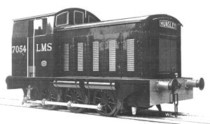 Reference has previously been made to the application of welded steel frame versions of the Heavy Duty Diesel for rail traction. A 6 cylinder VXS engine, with a rating of 412 bhp at 750 rpm, was fitted in an experimental locomotive, LMS 1831. Believed to have been the first diesel powered locomotive built for a British railway company, No 1831 was built by the LMS Railway and entered service in 1932. A second LMS diesel locomotive, No 7054, was built by the Hunslet Engine Company of Leeds in 1934. This was fitted with a smaller version of the VXS, a 6 cylinder VZS with an output of 198 bhp at 900 rpm. The locomotives had hydraulic and mechanical transmissions respectively.
Right: Locomotive 7054 built for the LMS Railway in 1934 by the Hunslet Engine Company.
In hindsight, Paxman's early involvement in diesel rail traction was an excellent move. In time it led on to the Company becoming a major player in a large new and profitable market which developed post-War. Other pre-War Paxman-engined locomotives were mainly small industrial shunters. However, in the late 1940s and early 1950s Paxman was to become one of the best known suppliers of engines for locomotives during the dieselisation of the British rail network and of many overseas railways. The rail traction market remained an important source of Paxman business right up to the end of the 20th century. That story is told on the pages Diesel Rail Traction and Paxman Diesels for the World's Railways.
Water Pumping
Paxman sold a good number of its earlier Heavy-Fuel-Oil engines to municipal water undertakings and pumping stations. This market also yielded a useful number of sales for the Heavy Duty Diesel Engine range.
Listing of Individual Engines and Their Customers
Details of Order Numbers, engine types and customers for many of Paxman's Heavy Duty Diesel Engines are to be found on the Oil Engine Listing page.
Surviving Examples
As far as I know there are only three surviving Paxman Heavy Duty Diesel Engines, all three of which are in Australia. One is a 5VZ type, No 24054, in preservation with the Central Goldfields Historic Machinery Society at Dunolly, Victoria, and awaiting restoration. The second, a 4VZ, No 24413, is in preservation at the Pioneer Park Museum, Griffith, NSW and is the only example currently in working order. The third, a 3VZ, is believed to be No 24564. This was purchased by David Rossington in late September 2017. Details of these engines, together with photographs, can be found on the page Paxman Diesels in Australia. If anyone knows of any other surviving example(s), I would be grateful if they could please contact me with details.
The Next Generation of Paxman Diesel Engines
The Heavy Duty Diesel Engine had only been on the market for a year or so when another watershed was reached in the story of Paxman's diesel engine development. 1932 was the year of AGE's financial collapse which brought down Paxman in its wake. No doubt the Company faced a great deal of uncertainty and disruption while new financial backing was sought to allow the business to continue and a new Board of Directors appointed. Edward Paxman now joined the Board as Engineering Director. Despite all the upheaval caused by AGE's fall, Paxman had the vision, motivation and energy to start developing its third generation of compression-ignition engines. The design of Paxman's first high speed diesels was undertaken in collaboration with Sir Harry Ricardo. The story of these engines and their successors is told on the page Paxman Engines since 1934.
Appendix A
Advantages of the Paxman Heavy Duty Diesel Engine, and Specification, as published in the booklet Paxman Heavy Duty Diesel Engines, Paxman Publication 1022, undated but no earlier than July 1933.
The Paxman Heavy Duty Diesel Engine.
In addition to incorporating the well proved features of Total Enclosure, 4-Stroke Cycle, Full Pressure Lubrication, referred to below, the Paxman Heavy Duty Engine embraces also a number of unique advantages which are of material benefit to the user. These include: -
Accessibility. Although all moving parts except the flywheel are totally enclosed, the construction is such that they are immediately accessible when required. Sliding or light removable covers give instant access to the valves and their operating gear and the camshafts. Very large but light doors on the crank chamber on being removed permit of full access to the crankshaft, bearings, and connecting rods.
Removal of Pistons. Pistons can be removed through the crank chamber doors. There is no necessity to remove the cylinder heads or disturb the manifolds or valve gear, or to drain the cylinder jacket. It is only necessary to uncouple the large end bearing, then lower the piston and connecting rod bodily into the crank chamber, when it can be removed in one piece together with its rod. (NOTE : The pistons are not split). The time taken for removal, after uncoupling the large bearing, is inside two minutes, and the piston can be as quickly and easily replaced. In practice this means that removal of the pistons from the Paxman Heavy Duty Engine is even simpler and quicker than in an horizontal engine of the open type, and is of the greatest importance in modern installations where multi-cylinder engines are installed. It reduces maintenance time and costs to a figure far less than has hitherto been the case.
It is not necessary to lay up an engine for a considerable time when pistons require withdrawing. They can be as easily and quickly removed and replaced as the valves in their cages, with the result that the engine can be kept continuously in service for periods far longer than has hitherto been possible. A further advantage of this method of removing the pistons is that no head room or lifting tackle is required above the engine. It is therefore possible for the engine to be installed in situations not otherwise suitable for vertical engines.
Handling of Parts. It will be appreciated that with the multi-cylinder medium speed engine the weight and size of each of the moving parts for a given horse power is very much less than that of the older types of engine. Therefore the parts are handled much more easily and removed and replaced much quicker. The cost of parts is considerably reduced whilst their life is longer due to the perfect lubrication and the reduction of heat stresses.
Total Enclosure. The Paxman Heavy Duty Engine is designed to run satisfactorily for long periods under any conditions. Therefore, all moving parts, with the exception of the flywheel, are entirely enclosed by light dustproof covers. This prevents the ingress of any dust or moisture in the air which could cause wear. It also permits of the employment of full pressure lubrication not only to the main working parts, but also the valve gear and other details so that all are always working under ideal conditions, consequently requiring only the minimum of adjustment and no attention when running. Furthermore, it results in the engine as a whole possessing a clean and attractive appearance and prevents any fouling of the surroundings in the engine room.
Smooth Running. A multi-cylinder medium speed engine is extremely smooth and even in operation. It can be run under conditions requiring complete absence of vibration and noise, as in Hotels, Offices, Ships, etc.
Ease of Operation.
To Start: Operate the master starting valve and move over the fuel control lever as the engine gathers speed.
Running: When full speed is reached the engine automatically comes under the control of the governor and no further attention is required.
To Stop: Pull back the fuel control lever.
In Publication 1042, the above paragraphs about Starting, Running and Stopping have been amended to read as follows:
To Start: Open the master starting valve. As soon as the engine is running on fuel, close the valve.
To Stop: Pull out the Fuel Pump cut-out lever.
It will be seen from the above that the Paxman Heavy Duty Engine can be operated by the most unskilled labour and with as great ease as an electric motor.
4-Stroke Cycle. Like the Paxman Slow Speed Vertical Type, these Heavy Duty Engines operate on the 4-stroke principal thereby ensuring absolute reliability, continued economy in operation, and guaranteeing greatly extended life of the working parts. There are no automatic valves, no crankcase compression, no separate scavenge pumps and no ports in the cylinder liners.
Piston rings therefore do not travel over ports and are not swept by the incoming and outgoing gases, but operate continuously against the cool and well lubricated cylinder walls.
In service this results in the wear on 4-stroke cylinders being on an average only about one-quarter that of 2-stroke Engines of the same size. Use is made of the expansion of the charge until the end of the stroke, there being no necessity to release the pressure through ports before the whole of the useful work is performed.
Pressure Lubrication. Full pressure lubrication by cool oil is copiously supplied to all parts instead of the sparing supply by mechanical drip feed lubricators necessitated on open type or 2-stroke crank case compression engines, which waste or suck the oil into the cylinder.
Reversal of load on the bearings of 4-stroke Engines, together with full pressure lubrication, ensures that the oil film on the surface is continually renewed. This thorough lubrication preserves the working parts from wear and results in long life and reduction in maintenance.
Standby Sets. Engines can be arranged for automatic starting in conjunction with special relay gear when they form the ideal unit for standby sets in Hotels, large Theatres, Workshops, etc., etc., being specially designed to come into operation automatically on the failure of the main supply.
Publication 1042 also contains the following section about the VY and VYL series of engines:
The Paxman Heavy Duty Diesel Engine - "VY" & "VYL" Series.
Engines of the VY and VYL series are designed for a normal output of 100 B.H.P. per cylinder at a range of speeds between 500 r.p.m. and 330 r.p.m. The importance of this provision will be appreciated since the engine can be constructed to run at the speed best suited to the driven machine while maintaining the full output. Any reduction in the speed below 500 r.p.m. is accompanied by an appropriate lengthening of the piston stroke as a means of obtaining the desired power. Engines of this type with increased stroke and reduced speed are termed "VYL."
While retaining the main features of the VZ and VX series, the VY and VYL engines differ from the former in several respects.
They are provided with a single camshaft which operates the valves by means of rocking levers. The suction and exhaust valves are disposed vertically in the cylinder heads and are fitted in easily removable cages.
There is a separate fuel pump for each cylinder, mounted above the camshaft in close proximity to the respective fuel injectors. These pumps are operated by cams and rocking levers, and the governor control mechanism provides for individual adjustment of each pump.
In the design of the cylinder heads - which are steel castings - particular attention has been given to the rapid dissipation of heat. The flow of cooling water is so guided that it is brought into contact with every part of the cylinder head. Moreover the internal construction of the cylinder heads is such as to practically eliminate heat stresses by permitting expansion of the heated parts to take place without transmission of stress.
The main construction is similar to that described on the foregoing pages, being the totally-enclosed Mono-bloc type with fully forced lubrication, chain drive to camshaft with provision for adjustment of tension and accurate adjustment of the timing, fully floating piston pins, completely enclosed forced lubricated valve gear, automatic air starting valves and simplified control. The pistons, as before, are removed through the crank case without disturbing the cylinder heads.
Specification
Crankshaft. The crankshaft is forged in one piece from the highest quality steel, and is machined all over. All bearings are of ample size to ensure long life. Journals and crank pins are ground, giving the highest possible finish and accuracy. The proportion of the shaft as a whole is so calculated in relation to the moving parts that there is no tendency for vibration to be set up, whilst the throw of the crank pins and the equal setting of the cranks are given the greatest attention to ensure good balance. The stiffness of the webs, the rigidity of the solid forged coupling and the proportioning of the end bearing to carry the flywheel weight, ensure correct alignment and absence of whip. Adequate thrust collars, copiously lubricated are provided to locate the shaft, full provision being made for variations in length due to the working temperature.
The Framework. The framework consists of a deep bedplate carrying the main bearings, and separate "A" frames which support the cylinder block. The cylinder block is tied to the lower part of the bedplate by high tensile through bolts which pass through the "A" frames and are tightened up to an initial degree greater than the tension which can be imposed upon them by the firing loads of the engine. They then absorb the whole of the working load without further extension.
As a result of the cast-iron framing being always in compression and not in tension, the greatest rigidity is obtained and the inspection doors can be kept very large without in any way detracting from the strength.
Both on the cylinder block and the bedplate, machined key-ways run the full length of the engine on either side, absorbing all lateral thrusts and maintaining perfect alignment of the cylinders and the crankshaft.
The main bearing shells are turned and are lined on the working surfaces with highest quality white metal to our own Diesel Specification. They are retained in position by steel caps, and the bottom halves can be turned out from under the crankshaft for inspection. The bearing surfaces are suitably grooved and channelled to maintain continuous lubrication over the working surface. The end main bearings are of increased size to withstand the extra load imposed by the flywheel and drives. A thrust bearing is provided, with large surfaces, full provision being made for expansion under working temperatures.
Cylinder Liners. The cylinder block is accurately bored by the use of jigs. Separate liners are inserted from the top, making a metal to metal joint with the spigotted recess and being free to expand at the lower end under temperature variations. They are cast in our special wear-resisting Diesel steel mixture, and are rough bored and turned, heat treated, seasoned, and finally finished-machined to dead size. They are free from ports, holes or studs which tend to set up distortion and excessive wear.
Pistons. Pistons are of hard close grained cast-iron, heat-treated and ground. The proportioning of the piston and rings is such as to ensure a gas tight seal with a minimum of friction and the maximum dispersion of heat to the liners, resulting in the best and coolest working conditions, efficient lubrication and long life.
Gudgeon Pin. The gudgeon pin is of case hardened steel, ground all over, and is of the fully floating type, being free to revolve both in the small end bearing and in the piston bosses. This prevents distortion of the piston under any working conditions, reduces to the minimum wear of the piston pin and small end bearing, and entirely prevents "chatter" in the gudgeon pin bosses. Consequently, this type of pin enjoys the longest life while being extremely easy to remove and replace without suffering any violence as in the case of the fixed type.
The small end bearing bush is carried in the solid eye of the connecting rod thereby avoiding the use of small end bearing bolts. The bearings are pressure lubricated from the main system.
A plate bolted to a machined face under the piston crown keeps lubricating oil from reaching the inside of the crown and carbonising, and protects the small end bearing from heat radiated from the piston.
Connecting Rods. The connecting rods are of high grade forged steel, machined all over in jigs, thus ensuring identical dimensions and perfect balance. All pistons and connecting rods are exactly matched for weight to a standard to ensure good balance of the reciprocating parts.
The large end bearing is of the highest quality anti-friction metal, with steel caps, secured by four fitting bolts of high tensile steel provided with stretching lengths between the fitted portions.
Cylinder Heads. The cylinder heads, which are cast of special steel mixture and fully annealed, make a spigotted metal to metal joint with the top of the liner, being clear of the cylinder block, they are machined to receive the air and exhaust valve cages, the detachable starting and relief valves, and the atomizer. They carry indicator fitment, adequate cleaning covers and water connections.
The cooling water from the liner flows direct to the cylinder head and passes over the whole of the head surface before reaching the outlet. Air and exhaust manifolds are bolted to the heads and the exhaust manifold, where not water cooled, has expansion joints to relieve the heads and piping of strain. The cylinder heads are machined to limit jigs and are thus interchangeable, as are also all parts of the valve gear, valve boxes, atomizers, etc.
Valve Gear. The air and exhaust valves are fully machined from silchrome forgings manufactured to our specification. This special steel possesses great resistance to heat and erosion and to wear on the stems. This combined with adequate lubrication results in long life.
The valves are carried in separate cages, which can be remove without disturbing any other part, thus facilitating grinding-in. Spare valves and cages, ground in ready for use, can be carried and installed in a few minutes, leaving regrinding of the removed valves to any convenient time.
Starting Valves. Starting valves, carried in boxes mounted on the camshaft, are automatically brought into contact with their cams by the admission of the starting air. They are opened in the correct sequence and admit the compressed air through short pipes to automatic non-return valves in the cylinder heads.
Relief Valves. Spring loaded relief valves are fitted to cylinder heads thereby protecting the working parts from pressures above the normal. The springs are protected by suitable shields.
Atomizers. These are of the fully automatic pressure operated type and require no attention in service. They are secured to the head by a robust easily detachable holder.
The construction of the atomizers is such that the jets do not foul up under any conditions of load and the engine can be left running light or with no load at all for long periods if required. The spray is most carefully proportioned to the combustion chamber and the degree of turbulence of the air inlet. As a result of this, excellent combustion is obtained together with quiet running and good consumption of fuel.
Camshafts and Valve Operating Gear. Exhaust and air valves are operated direct by rockers carried in their cages. These rockers carry rollers at one end which bear upon case hardened and ground cams on the camshaft. The camshaft itself is supported in gun metal bushed bearings which are pressure lubricated. No hand oiling is required since the whole of the valve gear is lubricated under pressure from a secondary pressure lubrication system of clean oil which is drawn from and returned to the camshaft trays. These trays are continued well above the level of the camshaft on either side of the engine. Above these trays are provided readily removable covers which enclose the whole of the valve gear, thereby entirely protecting the same from the ingress of dust or dirt, and at the same time preventing the copious lubrication from escaping.
Camshaft Drive. The camshaft drive is arranged at the flywheel end of the engine and therefore runs with exceptional steadiness. The chain drive, of very generous proportions, is taken from a sprocket on the crankshaft. On engines with two camshafts the drive is to a lay shaft and thence through machine cut spur gears to the two camshafts, one on either side of the engine. On engines with single camshaft, the chain drive is taken direct to a sprocket carried thereon. In all cases the whole system is entirely enclosed and pressure lubricated. Full provision is made, by a large jockey sprocket running on ball bearings, for the adjustment of the driving chain. Provision is also made for accurate adjustment of the timing of the camshafts relative to the crankshaft. All parts of the camshaft driving gear, although totally enclosed, are fully accessible for inspection, adjustment and renewal.
Fuel Pumps. The fuel pumps are of patented construction. Except on the largest size engines, separate fuel pumps for each cylinder are all assembled in a mono-bloc body provided with its own ground camshaft running in an oil bath and the whole assembly driven from an extension of one of the main camshafts, through a universal coupling provided with means for variation of timing. On the largest engines separate fuel pumps are mounted adjacent to each cylinder and driven direct from the main camshaft. The construction of the fuel pumps is such as to ensure extremely accurate metering of the fuel to each cylinder at all loads, resulting in smooth running. The control of the fuel supply is effected by the rotation of the pump plungers which require the minimum effort from the governor and results in very rapid and accurate governing.
The pumps require no adjustment or attention in use; full provision is made for adjustment or replacing of all parts of the pump when required.
Lubricating Oil Pump. The main lubricating oil pressure is provided by fully machined, valveless, gear pumps, the rotors of which are forged solid with their shafts. They are entirely automatic in operation and are provided with adjustable relief valves, the setting of which controls the oil pressure.
The lubricating oil pumps are of exceptional capacity and extremely robust construction, and are therefore well able to maintain the ample supply of lubrication to the engine under even the worst conditions.
The pump bearings themselves are pressure lubricated. By means of a special drive the main pump can be used for flushing through the system with lubricating oil before starting up or for drawing off oil from the bed when it requires to be changed. The pump is entirely enclosed and driven direct from the crankshaft and requires no attention in use.
Lubricating Oil Cooler. Where conditions necessitate a lubricating oil cooler, a separate external cooler of the multitubular type is provided. The arrangement of this cooler is such that the cooling water passes through the tubes on its way to the cylinder jacket. The oil is directed by baffles across the tubes and at right angles to their surface. This is the only means by which the lubricating oil can be properly cooled. If the oil is allowed to flow through the tubes only imperfect cooling can result, since it immediately forms insulating layers along the surface of the tubes, which prevent the main flow from cooling. The oil cooler is readily dismantled for inspection, the whole of the tube nest being uncovered so that it can from time to time be easily cleaned.
Flywheel. The flywheel is of the solid disc type with machined rim and coupling faces and is bolted direct to a coupling forged solid with the crankshaft; thereby the use of keys, which invariably tend to throw the flywheel proud of the shaft and out of balance, is completely avoided; the use of flywheel keys, although cheaper, is to be strongly deprecated on Diesel engines of the highest class.
The flywheel is centred on a spigot turned on the shaft itself and serves as a half coupling to be connected to the driven machinery. All flywheels are carefully balanced in special ball bearing mountings before being fitted to the engines, and are such as to ensure steady running under all conditions. Suitable barring holes or racks are provided on the rims.
Circulating Pumps. When carried on the engine, circulating pumps are of the centrifugal type driven through pressure lubricated machine cut gears from the crankshaft. They force the cooling water first through the oil cooler and then through the cylinder jackets. A regulating valve is provided to enable the temperature and amount of the water passing, to be adjusted to meet any conditions.
Note: Certain points of design vary in detail with the different size of engine. Such differences are dictated in every instance by the requirements of the design in the different sizes to give the Paxman efficiency, accessibility and reliability. In all cases, the main features of the framework, accessibility, total enclosure and pressure lubrication are maintained.
Paxman Steel Frame Engines
Constructed under license from C. H. Stevens.
British Patent Nos. 342610 and 362759. Patented in all principal Foreign Countries.
As an alternative to the cast-iron and through bolt construction the Paxman Heavy Duty Engines are also built with an All-Steel Fabricated Frame. The general construction of this framework is indicated in the photograph.
The design of the framework is such that the whole of the firing stresses is taken direct from the cylinder head right down to the seating of the crankshaft bearings in continuous steel plates without any load being imposed on the welding.
The simplicity of construction and the great accessibility to all parts of the framework ensure a perfect job being made of the welding throughout. There are no hidden or inaccessible welds and no welds subject to main running stresses. As a result of these features the framework, although exceptionally light, is immensely strong for all portable or semi-portable uses. For locomotive use and for marine use where weight is important, as in naval construction and Shallow Draft Vessels, the Paxman-Stevens welded framework construction is ideal.
Right: Paxman Steel Framing in course of construction, showing continuous sling plates.
The weight of the framework itself is less than half the weight of the equivalent cast-iron through bolt construction.
The strength of the steel frame is in every way equivalent to that of cast-iron.
By the employment of this unique construction, of which we are the pioneers, welded framework can be successfully employed to save weight whilst preserving all the unique features of the Paxman Heavy Duty Engines.
If required, the framework can be extended to embody in one piece the bedplate, generators, reverse gear, &c., as may be required.
To differentiate between the cast-iron and steel frame types the letter "S" is added to the engine mark shown in the tables on Page 19 of the steel frame engines, e.g., "VZ" indicates cast-iron construction, "VZS" indicates similar size of engine with steel framing.
It will be appreciated that with even the most fool-proof of framework design, employment of only the highest class of skilled welders is essential.
In our works we have been accustomed to the manufacture of welded structures of all kinds and sizes for very many years. We have constructed hundreds of welded boilers, engine beds, &c., and are therefore able to guarantee our workmanship.
We were the first firm in this country to construct Diesel engines with entirely welded steel framework, and our experience therefore is unique.
The general dimensions of the steel frame engine are identical with those of the cast-iron, but their weights are, of course, considerably less.
References
1. Heavy-Fuel-Oil Engines, Paxman Publication 987 (c.1931), p.47.
Motor Ship, July 1931, p.137.
Motor Ship, September 1931. p.247.
2. Engineering, July 17, 1931.
Motor Ship, September 1931. p.247.
3. British Patents, numbers 342610 and 362759, see:
Paxman catalogues Nos 1022 and 1042, Heavy Duty Diesel Engines, p.13.
4. Motor Ship, January 1938. p.88.
© Richard Carr 2006
Page updated: 05 Feb 2024 at 14:38