
Paxman "Peache Patent" Steam Engines
Introduction
Paxman's "Peache Patent" was a high-speed, single-acting compound steam engine, first exhibited by the Company in 1895. It was specifically designed for electrical power generation and used almost exclusively for this purpose. The Peache was built only by Paxman, which produced about 260 of these engines by the time the last one was made in 1913.
The Early Days of Electric Lighting
James Paxman, the Company's founder, got involved in providing steam engines to drive generators for electric lighting in the early days of the technology. He assiduously cultivated relationships with the leading consulting electrical engineers of the day, such as Colonel R E B Crompton and W H Massey; influential men who advised clients on installations and the equipment they should purchase. Paxman supplied an engine for the 1882 International Electric Light Exhibition at Crystal Palace where it was used for trials of dynamos. He went on to supply steam engines and boilers for electric lighting at other major national and international exhibitions in the early 1880s. Having established a name for himself in this field, Paxman supplied many steam engines and boilers for generating facilities installed in large houses of the rich and famous and in a number of institutions. During the 1880s and early 1890s electric lighting was an expensive luxury, very much the preserve of the wealthy.
The period from 1896 to 1904 was a time of considerable expansion in the provision of electric lighting. From the mid-1890s a growing number of local authorities established 'electric light stations' to supply electricity to the public. The favoured arrangement for generating in these stations was to employ small high-speed steam engines in multiple units. The high-speed engine was preferred because it allowed the use of smaller, and therefore cheaper, dynamos and alternators. However the conventional double-acting steam engines of the time tended to suffer from 'knocking' problems in their bearings when run at high speeds. The solution adopted was the use of single-acting engines. The most successful and popular of these was the Willans 'central valve' engine manufactured by Peter Willans and his partner Mark Robinson at Thames Ditton. James Paxman was acutely conscious of his Company's need for a high-speed engine if he was to continue competing in the power generation market and he was increasingly under pressure from his consulting engineer contacts to offer one. In 1893 James Courthope Peache, who had previously worked for Willans & Robinson, approached James Paxman with his own design of a high-speed single-acting engine.
James Courthope Peache
The designer of the Peache engine was a man of substantial private means which allowed him to be 'his own man'. His grandfather, also called James Courthope Peache, had been a very successful and wealthy London timber merchant. When Courthope senior died, his great wealth passed to his younger son, the Revd Alfred Peache, as the elder son died within six weeks of his father. In turn, Alfred's son, Courthope Peache junior, came to enjoy a substantial private income and greater freedom to make choices about the course of his career than might be open to a man more dependent on his employers.
The Revd Alfred Peache, and his unmarried sister Kezia, both generous benefactors to the Church of England, owned Layer Marney Tower from 1869 to 1899. Layer Marney Tower is an impressive Tudor property about 6 miles south-west of Colchester, now a major tourist attraction. Alfred became Lord of the Manor of Layer Marney and died in November 1900, at the age of 82, at his home, Danmore, in Wimbledon, London.
Courthope Peache junior was born on 5th February 1852 and graduated in Engineering from King's College, London. He joined Willans & Robinson in July 1885 as Works Manager of their Ferry Works at Thames Ditton. After nearly all the factory had been destroyed by fire in 1888, Peache was mainly responsible for the design and construction of the new factory. In his approach to manufacturing he was keen on standardisation and the interchangeability of components, as were his employers, and this trait showed through in the meticulous drawings maintained at Paxman for his engines. Despite his abilities and contribution to the Willans business, he was not offered a partnership and some friction appears to have developed between himself and Peter Willans. He resigned from Willans & Robinson at the end of January 1892.
Early in 1893, Courthope Peache wrote to James Paxman, seeking to interest Paxman in the high-speed engine he had recently designed. The timing was opportune as Paxman was becoming increasingly aware of his need for a high-speed engine. However, Paxman was not initially impressed by the design and could not see any great advantages in it. He sent the drawings to W H Massey, a respected authority on power generation, seeking his opinion. After considering Massey's reply, James Paxman decided to pursue the matter. Lengthy negotiations followed, leading to Paxman's agreement to build Peache's engines and the appointment of Courthope Peache as Paxman's Works Manager. After two years of development work on the engine and six months of running trials, three of the new engines were put on display at the Empire of India Exhibition held at Earls Court in 1895.
In 1896 Peache withdrew from day-to-day involvement in the running of the Paxman business and became "Consulting Engineer to Davey, Paxman & Co". However, he cannot have been too remote from life at Standard Works on Hythe Hill. In 1898 Harry Broom, who had finished serving his apprenticeship with Paxman, decided to set up business with Jethro Wade, one of Paxman's foremen. Peache offered to help them if they were short of capital. Initially they declined the offer, deciding to rely on their own resources. Later they were helped with a loan from Peache when they put up more buildings and started building compressors. This venture became the highly successful and well-known Broom & Wade compressor business. (1) Peache himself became Chairman of Broom & Wade for many years until relinquishing his interest in the business in 1914.
In 1899 Courthope Peache purchased Layer Marney Tower from his father. Whilst living at Layer Marney, Peache completed the north-west wing of the house and installed the smallest size Peache engine, a single crank SCcl, to generate electricity for lighting his home. The order, No 6050 was placed in March 1900 and the engine was despatched to Layer Marney on 28th February 1901
Peache sold Layer Marney Tower in 1904 and left Colchester to rejoin his old company, Willans & Robinson, which had by now moved from Thames Ditton to a large purpose-built factory at Rugby: the well-known 'Willans Works'. Joining as a Director in 1904, he was appointed Managing Director in 1908. Peache resigned this position in 1911 and became Chairman: a post he held until February 1920. He died at Haywards Heath, Sussex, in 1931 aged 79.
Main Features of the "Peache Patent" Engine
- Inverted Vertical. Like most vertical steam engines, the cylinders were aligned vertically, with the crankshaft located below them. However, the Peache was unconventional in that the centre line of the crankshaft was not directly below the centres of the cylinders. The crankshaft was set a little to the front of the engine. The advantage claimed for this arrangement was that it gave a nearly straight connecting rod during the downward working stroke, when the pressures were greatest, and kept any pressure due to the angle of the connecting rod on the back crosshead slide. The design was such that during the upstroke the small pressure transmitted to the crosshead slide was still on the back slide, thus reducing wear and avoiding knocking.
- High-Speed. As previously explained, in the closing years of the 19th century and the early years of the 20th century, high-speed engines were the favoured prime-mover for central power stations. High-speed engines allowed the use of smaller and less costly dynamos and alternators than were required with low or medium speed engines. In this context 'high-speed' was relative to the speed of other contemporary types of steam engine. The smallest 3-crank Peache could run at a maximum of 650 rpm while the standard speed of the largest was only 280 rpm.
- Single-Acting. A problem with conventional double-acting steam engines of the time, when run at high speeds, was 'knocking' in the bearings. In the double-acting engine both the forward and return strokes of the piston are 'power' strokes, imposing their full force first on the surfaces of the upper sections of big-end bearings and crankshaft journals and then on those of the lower sections. This, together with the greater inertial forces acting in the connecting-rods of a high-speed reciprocating engine, led to greater wear on the top side and under side of bearings and journals, resulting in backlash and 'knocking'. In a single-acting vertical engine only the downward stroke is a power stroke and knocking is avoided by maintaining the balance of pressure towards the crankshaft even during the up-stroke. A fuller discussion of the merits and disadvantages of the single-acting engine can be found in Appendix A.
- Three-Crank, Two Crank and Single Crank. By far the greatest number of Peache engines built were 3-crank types. Basically these comprised three vertical tandem compound engines connected to a three crank crankshaft, the cranks being offset at 120° to each other. The three crank arrangement was promoted as advantageous "both on account of the absence of vibration and even turning obtained" with this type. Single-crank types, producing up to 50 bhp, were also offered. Paxman's price list claimed that the vibration set up in these was unlikely to cause trouble, while the price was considerably less than that of a three crank engine. Looking at the copy book order entries it would seem that only two 2-crank versions of the engine were built. The first, Order No 4555, was made for the exhibition at which the Peache was launched and subsequently sold to the Stowmarket Timber Co. The second, Order No 8878, was built in 1908 for Christ's Hospital Schools at Horsham, Sussex.
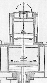
- Tandem Compound. Most tandem compound engines were horizontal types with two quite separate and distinct cylinders, one high-pressure (HP) and one low-pressure (LP), longitudinally in line with each other, not parallel to each other. The HP piston and LP piston were each mounted on a common piston rod linked to a single connecting rod attached to the crankshaft. The Peache was not unique in being a vertical tandem compound but most unusual in having the HP and LP cylinder castings bolted to each other with only the pistons separating the spaces inside each cylinder. The upper cylinder was of smaller bore than the lower and contained the HP piston. The lower cylinder was of larger bore and contained the LP piston. High pressure steam was admitted to the top side of the HP piston for the power stroke. The steam exhausted from the HP cylinder was then led to the underside of the LP piston for the return or up-stroke. The space between the two pistons was referred to as the 'controlling cylinder'. Its function was to balance the upward inertia force of the pistons, crosshead, connecting rod, etc, on the up-stroke so that a slight excess of pressure was maintained in a downward direction throughout the up-stroke.
Right: Detail of sectional view showing the HP and LP cylinders of the Peache's tandem compound arrangement and the HP and LP pistons mounted on a common piston rod.
Reproduced below is part of Paxman's "Peache Patent" 1905 Price List which contains a description of the engine. As that description is not particularly enlightening about the design and operation of the engine, more detailed and helpful descriptions have been added as appendices lower down this page. Appendix A is the description from William Ripper's Steam Engine Theory And Practice. (2) Appendix B is the description from Sydney Walker's Steam Boilers, Engines, and Turbines. (3) Appendix C has the description which appeared in Particulars of Exhibits by Davey, Paxman & Co Ltd, Engineers and Boilermakers, Colchester., a brochure specially prepared by Paxman for the 1901 Glasgow International Exhibition. Included in Appendix C are two sectional views of a 3-crank Peache, showing the general layout of the engine.
The July 1905 "Peache Patent" Price List – Paxman Publication No 57
The only Paxman publication close to a Peache engine catalogue, as far as I am aware, is the Price List of High-Speed Single-Acting Engines (Peache Patent), dated July, 1905. (4) Apart from the surviving Paxman copy order books it is the key primary source of information about these engines. Some of the text of the price list is reproduced below, including a List of Powers and Speeds of the different sizes and a Description of the engines. Most of the rest of the 47 page publication is taken up with:
- general layouts of each size of engine, giving dimensions for steam inlet, exhaust outlet, foundations and other dimensions required for planning installation;
- prices of both non-condensing and condensing versions of the engine;
- prices for delivery;
- prices of extras such as foundation bolts, indicator gear and tachometers;
- prices of bedplates, including the mounting of engine and dynamo and steam trials and testing at Colchester;
- gross shipping sizes and weights;
- lists of main parts and moving parts, schedules of kits of spare parts and a list of governor parts.
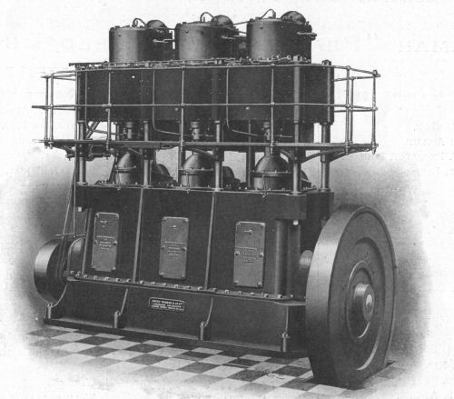
Illustration of a Size O Three-Crank Peache engine from the first page of the 1905 Price List.
The O size engine, with its 15" stroke, was the largest offered in the 1905 catalogue.
Designed to produce 750 bhp at 260 rpm, only one was built: Order No 6308 of April 1901.
"PEACHE" PATENT HIGH-SPEED ENGINES.
LIST OF POWERS & SPEEDS.
| Size | Stroke | Standard Speeds (RPM) | BHP at Standard Speed | Approx. KW at Standard Speed | Maximum Speed (RPM) | BHP at Maximum Speed | Approx. KW at Maximum Speed |
|---|---|---|---|---|---|---|---|
| S C | 4 inches | 700 | 10½ | 6½ | 750 | 11¼ | 7 |
| S D | 5 inches | 600 | 17 | 10½ | 650 | 18 | 11½ |
| S E | 6 inches | 520 | 25 | 16 | 560 | 27 | 17 |
| S F | 7 inches | 460 | 34 | 22 | 500 | 37 | 24 |
| S G | 8 inches | 420 | 47 | 30½ | 450 | 51 | 32½ |
| D | 5 inches | 600 | 48 | 31 | 650 | 52 | 33½ |
| E | 6 inches | 520 | 72 | 47½ | 560 | 78 | 51 |
| F | 7 inches | 460 | 100 | 67 | 500 | 110 | 73 |
| G | 8 inches | 420 | 140 | 95 | 450 | 150 | 102 |
| H | 9 inches | 400 | 190 | 130 | 430 | 200 | 140 |
| J | 10 inches | 375 | 245 | 165 | 400 | 260 | 175 |
| K | 11 inches | 350 | 335 | 230 | 370 | 355 | 245 |
| L | 12 inches | 325 | 420 | 290 | 340 | 440 | 305 |
| M | 13 inches | 300 | 515 | 360 | 310 | 530 | 370 |
| N | 14 inches | 280 | 630 | 440 | 290 | 650 | 460 |
| O | 15 inches | 260 | 750 | 525 | 270 | 780 | 545 |
NOTE: The Sizes of Cylinders are fixed by D. P. & Co., Ltd., to suit the conditions of each case.
PEACHE PATENT HIGH-SPEED SINGLE-ACTING ENGINE
DESCRIPTION
The Peache Engine is a High-Speed Single-Acting Engine.
The Steam Cylinders are carried on four wrought-iron columns. They are thus entirely isolated from the Working Chamber ; consequently the bath of oil and water does not get overheated and decomposed, no matter how long the engine is kept at work. No oil can be drawn from the working chamber to the condenser and boilers.
There are no internal glands in the Engine, and of the external glands one is subject to Low Pressure Steam only, and the other to Exhaust Steam only, this being one reason of the suitability of the Engine for working with Superheated Steam.
In case of water in the cylinders the Piston Rings act as Relief Valves and prevent damage.
Unless otherwise ordered, Engines will be made right-hand, i.e., as shown in outline illustrations, but, if necessary they can be made left-hand.
Every part of the Engine is readily accessible for examination or repair. The Working Chamber has large doors ;— Connecting Rod, Crosshead, and Valve Motion, or any of these parts can be readily disconnected and removed even in the smallest sizes without dismantling the Engine. The valves can be withdrawn by removing steam-chest cover only. Any H.P. Cylinder can be taken off by breaking one joint only, and both H.P. and L.P. pistons can then be removed without further dismantling.
The governor with its gear, also Steam and Exhaust Pipes are all attached to the main cylinder casting. Therefore, every part of the Engine is accessible without touching the Governor Gear, Steam or Exhaust Pipes.
EXPLANATION OF CATALOGUE
The Engine is made with three-cranks both on account of the absence of vibration and even turning that is obtained with the three-crank type of Engine.
A series of sizes of Engines are made, each size adapted to develop a certain standard power. For each size of Engine several types and sizes of Steam Cylinders are made to enable the standard power of the Engine to be developed to the best advantage that the pressure of steam and exhaust available admit of (see list). For each size of Engine the main parts remain the same whatever type and size of cylinder is adopted.
FULL-LOAD. In general the full-load is the maximum load for the Engine for continuous running. It is also the maximum load at standard expansion for the steam pressure available. It is at the same time the most economical load for the Engine to work at.
With steam pressures higher than those given in the list more than the listed power may be got out of the Engine.
With cut-off later than that best suited for economical steam consumption in each case, more power may be got out of the Engine than that given in the List.
The bearing surfaces and strength of parts in every Engine are sufficient to enable the Engines safely to take an overload of 25 per cent. above the full-load given in the List.
The full load that the Engine will develop varies with the speed. The most economical method of adapting an Engine to a given load is to adjust the speed (within the limits given in the List).
HAND EXPANSION GEAR to alter the point of cut-off while running, can be fitted when required. This Gear is useful where an Engine has to work alternatively on a vacuum and against atmospheric back pressure.
Engines for ELECTRIC TRACTION or POWER purposes :— The main requirement is a heavy flywheel between Engine and dynamo to prevent more than moderate fluctuations of speed under sudden changes of load. A 10 per cent. overload can be met by using a Supplementary Valve to admit steam from steam chests to the Receiver.
Overloading may also be provided for by providing a generating plant in which each unit has a capacity of 20 per cent. to 25 per cent. above the normal full-load which it is intended to develop.
This 20 per cent. to 25 per cent. overload can be met by raising the boiler pressure above that required to develop the normal full-load, and this is the course recommended where possible, on the score both of economy and simplicity. For instance, an Engine designed to develop its full normal load with 140 to 150 lbs. per sq. inch will develop 25 per cent. above its normal full-load if supplied with steam at a pressure of 190 lbs. per sq. inch. Fix the boiler pressure then at 200 lbs. per sq. inch. The engine throttle valve under control of the governor will, under normal conditions of load reduce this to 150 lbs. per sq. inch or less, the engine under these conditions getting the benefit of the consequent superheating or drying action on the steam, while to meet overload the full boiler pressure of 200 lbs. per sq. inch or so will be available at the Engine.
If it is not feasible to provide for overload by raising the boiler pressure above that desired for normal working, it will be necessary to choose a size of Engine that will give the 20 per cent. to 25 per cent. above the required normal full-load with the ordinary working boiler pressure. For instance, with 150 lbs. per sq. inch available at the boilers take an Engine that will give its full load with 120 lbs. per sq. inch, this Engine will then give an overload of 20 per cent. to 25 per cent. with 140 lbs. per sq. inch.
GOVERNORS. On each Engine a powerful and sensitive spring governor is provided, coupled direct to the throttle valve spindle. A hand Speed Adjustment Gear provides for a variation while running of 30 per cent in the number of revolutions per minute made by the Engine; while for any speed throughout this range for which the speed adjustment is set, the variation from full to no load will not exceed 3 per cent.
GENERAL. The figures given in the Catalogue are intended to serve as a guide only. In all cases it is best to write to Messrs. Davey, Paxman, & Co., Ltd., giving full particulars as to requirements, nature of work to be done by the Engine (viz., providing power for Electric Light, Electric Traction, or other purpose) together with pressures of Steam and Exhaust under which the Engine will have to work, when a quotation for the Engine best adapted to the work, and guarantees as to steam consumption, etc., will be promptly forwarded.
ENGINES FOR SMALL POWER
For small powers up to 50 horse power, a Peache Patent Single Crank Engine is made. For small powers the vibration set up by a Single Crank Engine is not likely to cause trouble, while the Price is considerably less than that at which the three crank type could be sold.
Quotations for single Expansion Engines will be sent on application.
In stations where a small set or sets are provided for the day load it is sometimes advantageous to put down Single Crank Engines for this purpose. These day load Engines can be chosen of the same size as the Main Engines, the working parts being thus interchangeable, while the power developed by each will be one-third that of the power of one of the Main Engines.
Peache Engine Orders and Installations
Page 2 of the 1905 price list of Peache Patent engines has a list of the 'electricity stations' where Peache engines had been installed, or were on order, as at July 1905. The text of that page is reproduced in Appendix D below.
The details of every Peache engine order, as listed in the surviving Paxman copy order books, are shown in Appendix E below.
Three installations equipped with Peache engines are described here; one in Australia and two of local interest.
Melbourne City Council's Spencer Street Power Station, Melbourne, Australia
Pictured below is the Peache engine installed at Melbourne City Council's Spencer Street Power Station in about 1900. Coupled to a 120kW alternator, it is believed to be No 10650, a Jc (non-condensing) 3-crank engine, built under Paxman Order No 5999 of 11th January 1900 and despatched from the factory on 27th June 1900. The cylinder bores were 10" (HP) and 15" (LP) and the stroke 10". The order was placed by Johnson & Phillips, a British electrical contracting and alternator manufacturing company. In the 1905 Price List the Jc is stated to have a standard speed of 375 rpm, producing 245 bhp for 165kW output. The speed could be adjusted up to 400 rpm and down to 315 rpm. At 400 rpm it produced 260 bhp for 175kW output. The price, ex-works, of a Jc engine in 1905 was £782. (My thanks to Rohan Lamb of Melbourne for bringing this installation to my attention and providing the photograph.)
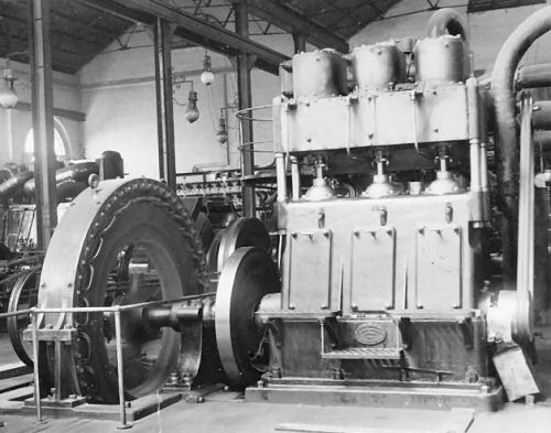
Peache 3-crank 'Jc' engine in Melbourne's Spencer Street Power Station.
Colchester's Electric Light and Power Department
The largest Peache installation by a local authority, and perhaps the best documented, was that at Colchester. It is no great surprise that the Corporation should have awarded the engine contracts to the town's largest engineering business whose founder was so influential in local politics and civic affairs. However, even in his home town James Paxman was not without competition when tendering to supply engines for the new Electricity Works. A fair amount of lobbying for the contracts took place behind closed doors. Ultimately no less than seven Peache engines were installed.
Colchester Borough's Electric Light & Power Department published a booklet in November 1902 recording the construction and development of its Electricity Works. (5) The original consulting engineer for the project was W H Massey who presented his first report at the end of January 1894. His second report was presented a few weeks later, in May, but at a meeting in October that year the Council decided to take no further action. The whole question was discussed again on 4th December 1895 and a decision to construct the Works was reached in January 1896. Siemens Brothers & Co of London, who were to supply the dynamos and other electrical equipment, were appointed as main contractors.
The first three Peache engines, Fc types, were ordered in June 1898 (Order No 5503) and despatched from the factory in September that year. Each was rated 110 hp at 500 rpm, had cylinders of 6½" and 11½" bore x 7" stroke, and was coupled to a 62kW dynamo. A type Kcc (Order No 5879), rated 360 hp (at 375 rpm ?), with cylinders 10½" and 19" bore x 11" stroke and coupled to a 225kW dynamo, was installed in August 1900. The fifth engine, a type Jcc (Order No 6251), was installed in November 1901. This was rated 260 bhp at 400 rpm, had cylinders of 9½" and 16" bore x 10" stroke, and was coupled to a 175kW dynamo, compound wound for lighting or traction. The five dynamos, all 500 volt machines designed and manufactured by Siemens Brothers, had a total output of 586kw.

Colchester's Electricity Works with its Peache engines and Siemens dynamos.
By the time the Electric Light & Power Department's booklet was published in November 1902, Paxman had also supplied four 'Economic' boilers, the steam range and two sets of condensing plants for the Works. Three of the boilers were 14' long x 8' diameter, with a working pressure of 140 psi, each capable of producing 6,000 lbs of steam per hour. The fourth was 14' 6" long x 9' 9" diameter, constructed for a normal working pressure of 180 psi and capable of producing 10,000 lbs of steam per hour. The steam range - the steam feed and exhaust piping system - ran the entire length of the boiler house. On the extreme wing the range started with an 8" steam main, increasing at the third boiler to 10". The main exhaust was 16" diameter cast iron piping. This traversed the engine room in a trench below the flooring and, turning into the boiler house at the north end of the building, crossed the condenser pit before rising through the boiler house roof to a height of 25 feet to exhaust to atmosphere. The two condensers and sets of pumps were fixed in the boiler house, in a pit 7' 6" below the level of the floor. The independent condensing plants had 700 and 800 square feet of cooling surface respectively.
The Electricity Works was situated off Stanwell Street and Osborne Street. The 1,023 square yards of the original site were purchased in 1897. General supply first commenced on 1st December 1898 and the Works was handed over to Colchester Corporation on 1st December 1900. By 1st November 1901 there were 203 consumers. A year later there were 303 consumers, representing 18,615 x 8 candlepower lamps. Because of the great increase in demand, it was decided to extend the Works. An additional 805 square yards of land adjoining the existing site were purchased in August 1901. On 3rd December that year the Council decided to purchase and install a 500 to 550 hp engine direct coupled to a 375 to 400 kW dynamo, wound for lighting or traction, to be ready for use by the autumn of 1903. Construction of the new extensions had commenced by late 1902. For the enlarged Works Paxman supplied two more Peache engines, both Mcc types, each rated 530 bhp at 310 rpm and having cylinders of 12" and 24" bore x 13" stroke. The first, Order No. 6960, was ordered on 13th February 1903 and the second, Order No. 7398, on 11th July 1904 but the surviving Paxman copy order books do not record when these engines were despatched from the factory.
Maidstone, in Kent, was another local authority with a large Peache installation. Between November 1899 and October 1903 it ordered six Peache engines, five Jcc and one Gcc condensing types, for its electricity works.
Parkeston Quay, Harwich
Another north-east Essex installation dating from about the same period as Colchester's Electricity Works, and featuring much identical plant, was a power generation facility at Parkeston Quay, near Harwich. On 4th May 1899 the Great Eastern Railway ordered from Paxman three Peache Patent size F condensing engines (Order No 5753), five 14' long x 8' diameter Economic boilers, and an independent surface condenser for Parkeston. All items were despatched from the factory during May 1900, apart from the condenser which was delivered about a year later. The dynamos were supplied by Crompton & Co who were responsible for the electrical engineering aspects of the project.
The Demise of the Peache Engine
There were a number of factors which led to the demise of the Peache, and indeed of the Willans high-speed single-acting engine. One was the development of a very successful high-speed double-acting engine by the well-known maker, Belliss & Morcom. They overcame the 'knocking' problem by adopting pressure lubrication of the crankshaft bearings. In the lower power ranges the Peache and Willans engines also faced growing competition from gas and oil engines. More importantly, with the expanding demand for electricity, power stations were turning to larger engines and the steam turbine was beginning to establish itself as a prime mover for power generation. From the full list of orders in appendix D it will be seen that after 1905 orders for Peache engines fell away sharply. Orders for 28 were received in 1905 but only 5 in 1906 and 4 in 1907.
No Survivors
We are not aware of any surviving example of a Peache engine but would very interested to hear from anyone who knows of one that is still around.
Appendix A - William Ripper on the Single-Acting Engine and the Peache
The following extracts are from the section entitled 'Quick-Revolution Engines' in Steam Engine Theory and Practice by William Ripper. (2) In the first extract Ripper outlines a disadvantage and the advantage of the single-acting engine.
(In) a "single-acting" engine the steam acts upon one side of the piston only. A disadvantage of this arrangement is that for a given power the cylinder capacity must be twice as great as in a double-acting engine, or else the engine must run twice as many revolutions per minute. The advantage of making the engine single-acting is that it may be run at the highest speeds comfortably, without any danger of knocking, and without the necessity for frequent adjustment of brasses, because in the single-acting engine the working parts are in a condition of constant thrust, that is, the piston-rod is pressed against the crosshead-pin, and the connecting-rod against the crank-pin, not only during the working stroke, but during the return stroke also. There is no tendency to knock, because there is no change of direction of force transmitted.
In order to secure that the condition of constant thrust is maintained, and that the connecting-rod and piston-rod are not flung away from their respective pins on the upper portion of the up-stroke, an amount of compression must be provided (either by the steam or by other means) which shall always cause a downward pressure in excess of the upward accelerating force.
Ripper goes on to discuss the Willans engine, a highly successful single-acting type which sold in large numbers, before describing the Peache engine. The text reproduced below was illustrated by a sectional view of the Peache which was identical, for all practical purposes, to one published on page 36 of the 1905 Price List and that shown in Appendix C below.
The Peache engine is another example of a good type of single-acting engine. The excess pressure is maintained on the pistons, in the direction of the crank-shaft, during the up-stroke, so that a constant thrust is maintained on all bearings both on up and down strokes, by means of the compression and subsequent expansion of steam in the space between the high-pressure and low-pressure pistons. Distribution of the steam is effected by a valve gear deriving its motion from a point on the connecting-rod. This valve motion provides for the placing of the valves in a convenient position at the back of the cylinders. There are no eccentrics on the crank-shaft, and therefore room is left for long and well-supported crank-shaft bearings. The crank-shaft and other working parts run in a bath of oil and water. The engine consists of three tandem compound engines combined and working on cranks at 120°. The steam is distributed to the two cylinders of each engine by a single piston valve. The steam enters by a branch, on the low-pressure cylinder-casting, and at the centre-line of the steam-chest, and passes right and left by passages formed in the casting to the other two steam-chests. At the top of the stroke the high-pressure piston uncovers two small bye-pass ports which communicate with the space underneath that piston, and thus for an instant at the top of each stroke the space called the controlling-cylinder is placed in communication with the high-pressure cylinder, and by this means the initial pressure of steam in the controlling cylinder is maintained at a constant proportion to that in the high-pressure cylinder.
In the condensing type engines, in which the ratio of expansion and range of temperature is large, a steam-jacket is applied to the controlling cylinder, so that the steam in the controlling cylinder becomes a medium for the transfer of heat from the steam-jacket to the working surfaces of the high-pressure and low-pressure cylinders.
To maintain a constant thrust on the valve-motion an air-buffer is adopted.
A feature of this engine is the position of the crank-shaft, which is placed in front of the cylinder-axis. This position is adopted to obviate reversal of pressure of the cross-head on the guides, which occurs in a single-acting engine with the usual position of crank-shaft. It will be seen that the connecting-rod is nearly vertical during the down-stroke, when the heaviest pressures are being transmitted by it, and that during the up-stroke, when the angle the connecting-rod makes with the piston-rod is large, the pressures transmitted are small, but the angle of the connecting-rod being always towards the back cross-head guiding surface, the resultant pressure is always on the back guide.
RESULTS OF TRIALS OF 150 HORSE-POWER PEACHE COMPOUND ENGINE.
Condensing. Non-condensing. Steam-chest pressure 94 lbs. 119 lbs. Revolutions 438 438 M.E.P. 40.01 42.96 I.H.P. 141 150.5 E.H.P. 124.3 128.0 Efficiency per cent. 88.3 85 Steam per I.H.P. per hour 18.4 22 Steam per E.H.P. per hour 20.9 25.8
Appendix B - Sydney Walker's Description of the Peache Engine
The following extract is from Steam Boilers, Engines, and Turbines by Sydney F Walker. (3).
The Peache high-speed engine, which is made by Messrs. Davey, Paxman & Co., is also single acting, and it has several important distinguishing features.
It is nearly always made with three cranks, and with two cylinders, high- and low-pressure, above each crank. A transverse sectional drawing of the engine is shown in Fig. 99 (virtually identical to the sectional view shown below in Appendix C). The crank-shaft works in a bath of oil and water, as in the other cases, and it has the special feature, that in place of being fixed directly below the centre line of the cylinders, it is out of line, a little to the front of the engine, the makers claiming that this gives a nearly straight connecting rod during the downward working stroke, and keeps a pressure on the back cross - head slide. The valves also are special to the engine are not worked by eccentrics, as is usually the case, but by the rocking lever shown in Fig. 99, working from a rod attached to and receiving motion from the connecting rod. As will be seen, the valve rod is fixed vertically, and works vertically, and moves the two valves, that controlling steam to the high-pressure cylinder, and that controlling steam to the low-pressure cylinder, by one operation. In addition, there is an air-buffer cylinder, that will be seen just above the rocking lever, which is employed to overcome the inertia of the valve at certain portions of the stroke, air being compressed at other portions, and giving up the energy delivered to it to overcome the inertia of the valve when required. As will be seen from the drawing also, the high- and low-pressure cylinders are virtually one, merely divided by the piston, and they are caused to act as high- and low-pressure cylinders by the distribution valves. The steam enters by the throttle valve, which is shown on the right in Fig. 99, into the space surrounding the valves, which forms the steam chest. From this it passes under the edge of the high-pressure valve, to above the high-pressure piston, and after it has forced the high-pressure piston to the end of its stroke, it is exhausted over the top of the high-pressure valve, down through the main body of the valve, and over the top of the low-pressure valve, to the under side of the low-pressure piston, forcing the low-pressure piston upwards, the high-pressure piston going with it, since, as will be seen, the high- and low-pressure pistons are on one piston rod. The space between the high- and low-pressure pistons is called the controlling cylinder, and is arranged to be connected and disconnected by the motion of the high-pressure piston, from the space above the high-pressure piston.
Hence, this space is alternately filled with steam at the same pressure as exists above the high-pressure piston, the steam is expanded, and is compressed by the upward motion of the low-pressure piston ; the object of the action in the controlling cylinder being to balance the upward inertia of the pistons, cross head, connecting rod, etc., on the up stroke, so as to keep a slight excess of pressure in a downward direction throughout the up stroke. The work done in compressing the steam in the controlling cylinder on the up stroke, is given out again on the down stroke, by the expansion of the steam, it acting upon the low-pressure piston, at the same time as the steam from the steam chest is acting upon the high-pressure piston. It is claimed that the arrangement of the valves behind the cylinders enables the space occupied by the eccentrics in other engines to be dispensed with, making the engine more compact. The engine has its crank chamber enclosed, with doors for access, the cylinders being supported from the crank chamber by steel pillars. It will also be noticed that the connecting rod works in a gland above the crank chamber, the gland forming the end of a dome-shaped cover, which prevents oil, etc., from passing upward.
The valve motion described is made for cut-offs from 0.4 to 0.5, from 0.5 to 0.6, and from 0.6 to 0.7 in the high-pressure cylinders, these are fixed cut-off gears. The engines are also made for adjustable cut-offs by automatic governors. The governor of the Peache engine acts on the throttle valve, as in the other cases.
Appendix C - Description of the Peache Engine in a 1901 Exhibition Brochure
The following description of the Peache engine was included in a brochure entitled Particulars of Exhibits by Davey, Paxman & Co Ltd, Engineers and Boilermakers, Colchester., specially prepared by Paxman for the 1901 Glasgow International Exhibition.
Davey, Paxman "Peache" High-speed Engine.
In the Machinery Hall will be found a fine example of a 360 Indicated Horse Power Davey, Paxman "Peache" High Speed Engine made by this firm. Although this engine is very well-known, being largely used in the United Kingdom, South Africa, India, China, &c., it may not be out of place to re-call the main features which have contributed to its great success.
The Engine is single acting, that is the balance of pressure is always towards the crank shaft, so that there is no back lash in any of the bearings. The Engine runs silently, and no matter how long the Engine may run without letting the bearings together, there can be no "knock."
The High Pressure steam chest consists of the annular space round the main body of the Valves, and is situated partly in the High Pressure cylinder casting and partly in the Low Pressure cylinder casting. Steam from the throttle valve passes to a branch on the Low Pressure cylinder casting, connected by passages in that casting to the three High Pressure steam chests. This construction has been adopted in order to permit of any High Pressure cylinder being removed without breaking any joint besides that between the High Pressure and Low Pressure cylinders.
 Following the distribution of steam to the cylinders :- Steam passes under the edge of the High Pressure valve to the top of the High Pressure piston, and is exhausted over the top of the High Pressure valve, down through the centre of the main body of the valve, and thence over the top of the Low Pressure valve, to the underside of the Low Pressure piston, and finally it is exhausted under the lower edge of the Low Pressure valve, to the exhaust chamber. In the bore of High Pressure cylinder, are cut two small bye-pass ports over which the High Pressure piston passes at the top of its stroke, thus placing the space between the High Pressure and Low Pressure pistons, in direct connection with the upper side of High Pressure piston. This space, which is called the Controlling Cylinder, is thus at the top of the stroke filled with steam at approximately the same pressure as that in the High Pressure cylinder; on the down stroke this steam expands, and on the up stroke it is compressed until at the top of the stroke it again reaches the pressure of the steam in the High Pressure cylinder, any small loss that may occur by leakage being made good by fresh steam passing from the High Pressure cylinder.
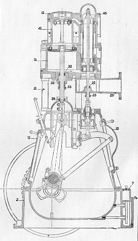
Right: Transverse sectional view of a Peache engine. To the right of the cylinders is the piston-valve gear.
The function of this controlling cylinder is to effect a balance of the upward inertia force of the pistons, crosshead, connecting rod, &c., on the up stroke ; that is, to keep a slight excess of pressure in a downward direction throughout the up stroke. Thus, on the up stroke, the steam acts on the under side of the Low Pressure piston, but instead of being allowed to act direct on the crank it does work in compressing the steam in the controlling cylinder, and in displacing the steam under receiver pressure from the High Pressure cylinder. The work thus done in compressing steam in the controlling cylinder is given out again by its expansion on the next down stroke, and the work done in transferring steam under pressure from the High Pressure cylinder to the receiver is utilized in the Low Pressure cylinder.
It will be noticed that the valves are always subject to receiver pressure, which tends to maintain them in constant downward thrust ; this, however, is not quite sufficient to overcome the inertia of the valve and its motion at the top of the stroke, and to supply this deficiency an air buffer cylinder is employed ; this is fixed in the working chamber.
The crank shaft is placed out of line with the cylinders. The reason for adopting this position is that it gives a nearly straight connecting rod during the downward working stroke, when the pressures are greatest, and keeps what pressure is due to the angle of the connecting rod on the back crosshead slide. On the upstroke, when the angle of the connecting rod is greater, the downward pressures are only sufficient to balance inertia forces of the reciprocating parts, and therefore although the angle of the connecting rod is considerable the pressure transmitted to the crosshead slide is small, and what there is is still on the back slide. That is the crosshead is kept always pressed against the back slide. If the crankshaft were placed, as is usual, in line with the axis of the cylinders, the crosshead (in a single acting Engine) would be alternately pressed against the front and back slides on the down and up strokes respectively, and any wear would produce a knock in those parts.
The valves are worked from a point on the connecting rod by means of a rod and rocking lever. These as well as the main parts are kept in constant thrust. This valve motion brings the valves into a convenient position, namely, at the back of the steam cylinders, so that the cylinder centres can be brought close together. At the same time there being no eccentrics on the crank-shaft, ample room is left for long and well supported bearings. The valve motion itself gives a better distribution of steam than could be obtained with an eccentric, namely - quick opening and cut off in the High Pressure Cylinder, later cut off in the Low Pressure cylinder, and very free and ample exhaust opening for the Low Pressure cylinder.
The working parts run in a bath of oil and water, all parts being constantly splashed over with lubricant ; a gauge tank at the back of the base shows the height of the lubricant bath.
 The steam cylinders are supported on four wrought-iron columns, and are entirely isolated from the working chamber. This construction has two important advantages. First - Heat cannot pass from the steam cylinders to the lubricant bath, and thus overheat and decompose it. Second - when running on a condenser, oil from the Working Chamber cannot be sucked up through the glands into the cylinders, and thus get to the condenser and boilers.
An inspection of the section will show that the Engine is extremely simple in construction.
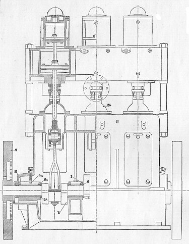
Left: Sectional front view of a 3-crank Peache engine.
There are no internal glands, and of the external glands, that on the valve spindle is subject to exhaust pressure only, while that on the Low Pressure cylinder is subject to a low pressure of steam only.
Every part can be readily got at for examination or renewal. The valves can be withdrawn by breaking the valve cover joint only. The High Pressure and Low Pressure pistons can be removed by breaking the High Pressure cylinder joint only, without interfering with any steam pipes or touching the governor gear.
All the working parts can be got at through large doors which are provided on the working chamber.
The Crosshead pin is a sleeve of hard cast iron with two internal cones, it is split along the top side and expanded into the crosshead by a bolt and two cones ; by slacking a couple of locknuts the crosshead pin can be readily withdrawn.
There is a strap under the connecting rod big end bearing, which is hinged to the connecting rod. By slacking the two locknuts in front, this strap can be swung back.
The valve motion can readily be removed by slipping out a couple of pins, and withdrawing the brackets on back of crosshead guide.
The piston rod screws into the cast-steel crosshead and is locked in place by a couple of set bolts ; this provides for adjustment of the clearances in the cylinders, as the bearings wear, thus doing away with loose packing pieces, or other primitive means of taking up for wear, and also providing a ready means for disconnecting piston rod and crosshead.
Caps are fitted over the main bearings. These can readily be removed from inside the working chamber, and the main bearings themselves, which fit into circular seatings, can be removed with the crankshaft in place.
An inspection of the drawing on opposite page (split into the two images which appear above) representing a section of the engine, taken in conjunction with the above explanations, will make it apparent that all the various parts in the "Peache" Engine are very readily accessible, as well as being strong and substantial in themselves, and that in these important respects the "Peache" Engine compares favourably with other High Speed Engines.
All working pins are case hardened and subsequently ground up. All bearings are either of phosphor bronze, or else have white metal surfaces.
All bearing surfaces are exceptionally large, reducing wear to a minimum and enabling the engine to take with safety the heaviest load which the steam pressure available can operate.
The Governor is of the centrifugal type, with the main springs connected directly across from one ball to the other, so that the friction of the governor is kept down to a minimum, the pins having only to carry the small pressures which come upon them from the actual work of moving the throttle-valve. The governor is capable of controlling the speed of the engine at all loads within one per cent. of the normal, and the normal speed can be adjusted by hand while the engine is running by as much as 30 per cent. without affecting the above-mentioned error.
Appendix D - Peache Engine Installations as at 1905
The following list is reproduced from page 2 of the July 1905 "Peache Patent" engine price list.
Central and other Electricity Stations
where the
Paxman "Peache" High-Speed Engines
are installed.
| Aberystwyth Bovril Ltd, London Bexley Heath Asylum Baltic M & S Exchange, London Birkbeck Bank, London Bo'ness Carnarvon Chelmsford Canton, China Cardiff P.O. Chepstow Chesham Christ's Hospital Schools, Horsham Colchester Consolidated Gold Fields of South Africa Ltd Clare Hospital, Suffolk Christchurch, New Zealand Cradley Heath Civil Service S. A., London Chiswick Dunlop Rubber Co, Birmingham Durban, Natal "Daily Graphic," London |
Delhi, India Earl's Court Exhibition Eastbourne Felix Hotel, Felixstowe, Suffolk Folkestone Fareham Great Northern and City Railway, London Hastings Heston and Isleworth High Wycombe Kennington Road Baths, London Kendall & Gent, Messrs Langho Colony, Blackburn Liverpool P.O. Leicester Grand Hotel London G.P.O. Morley Maidstone Meyer and Charlton Gold Mining Co Ltd Morecambe Musselburgh |
Melbourne, Australia Nottingham P.O. Natal Harbour Natal Railways Parkeston Quay, Great Eastern Railway Paisley Robinson Central Deep Ltd., Johannesburg St Pancras St Patrick's College, Maynooth Sandown, Isle of Wight Shanklin, Isle of Wight Southwold Salukine Mine, Rhodesia "Star" Office, London Subiaco, West Australia Tulliallan Castle, Kincardine-on-Forth Windsor Wolverhampton Welbeck Abbey Winchester House, London Yarmouth |
Etc. Etc. Etc.
Appendix E - Complete List of Orders for Peache Engines
Below are details of every Peache engine order listed in the surviving Paxman copy order books.
DATE FORMAT in the table below is dd-mm-yy, between the years 1895 and 1914.
ENGINE DESIGNATIONS: The lower case letters, which follow the upper case engine size letters, indicate different versions as follows: In the case of Single Crank engines "cl" = Non-Condensing Compound; "cc" = Condensing Compound. In the case of Three Crank engines "c" = Standard Compound; "cl" = Large Cylinder Compound; "cc" = Condensing Compound.
ORDER DETAILS below are basically as they appear in the Paxman copy order books except that abbreviations have been expanded to avoid ambiguity and aid understanding.
| Order No | Order Date | Description | Engine No | Customer | Where Sent | Date Sent |
|---|---|---|---|---|---|---|
| 4554 | 24-01-95 | 2. 3 Crank Tandem Compound High-Speed Vertical Engines. 10" + 15" x 10" | 8084/5 | London Exhibitions Ltd | ||
| 4555 | 24-01-95 | 1. 2 Crank Tandem Compound High-Speed Vertical Engine. 10" + 15" x 10" | 8086 | London Exhibitions Ltd (later at Stowmarket Timber Co.) | ||
| 4808 | 20-02-96 | Peache High-Speed Engine. 9" + 16" x 10" | 9004 | Crompton & Co Ltd | Yarmouth | 02-10-96 |
| 4888 | 23-04-96 | Jc Peache High-Speed Engine. 10" + 16" x 10" | 9064 | Crompton & Co Ltd | St Pancras Vestry | 16-12-96 |
| 4909 | 28-05-96 | Two Hc Peache Engines. 9" + 13½" x 9" | 9094/5 | Electric Construction Corporation | Durban Lighting | 21-04-97 |
| 4933 | 06-07-96 | Jc Peache High Speed Engine. 10" + 15" x 10" | 9123 | Electric Construction Corporation | Eastbourne | 07-05-97 |
| 4935 | 09-07-96 | 3. Fc Peache High-Speed Engines. 7" + 10½" x 7" | 9125/7 | Siemens Brothers & Co | Windsor | 26-01-97 |
| 4945 | 30-07-96 | 2. Dc Peache 3 Crank Engines. 5" + 7½" x 5" | 9138 | Crompton & Co Ltd | Chelmsford | 23-10-97 |
| 4961 | 31-08-96 | 5. Peache High-Speed Engines. 7½" + 13" x 8" | 9162 | Electric Copper Co Ltd | Lancashire | 07-09-97 |
| 4977 | 30-09-96 | D High-Speed Engine. 7" + 10½" x 7" | 9194 | Curtis Brothers Ltd | Charlbury, Oxon. | 11-06-97 |
| 4986 | 08-10-96 | Peache 3 Crank Single-Acting Engine. 7½" + 10½" x 7" | 9206 | Pneumatic Tyre Co Ltd | Coventry | 14-04-97 |
| 4996 | 26-10-96 | 2. Peache High-Speed Engines. | 9218/9 | Crompton & Co Ltd | Calcutta | 27-07-97 |
| 5029 | 08-01-97 | Three Ec Peache High-Speed Engines. 6" + 9" x 6" | 9265/7 | Crompton & Co Ltd | Hastings | 13-10-97 |
| 5048 | 22-01-97 | Jc Peache High-Speed Engine. 10" + 15" x 10" | 9293 | London Exhibitions Ltd | London | 17-05-97 |
| 5071 | 03-02-97 | Two Ec Peache High-Speed Engines. 6" + 9" x 6" | 9326/7 | Siemens Brothers & Co Ltd | Nottingham Post Office | 06-10-97 |
| 5074 | 04-02-97 | One Fc Peache High-Speed Engine. 7" + 10½" x 7" | 9330 | Thomas Parker Ltd | C.S.S. Association, London | 18-09-97 |
| 5076 | 05-02-97 | Dc Peache High-Speed Engine. 5" + 7½" x 5" | 9332 | Siemens Brothers & Co Ltd | Nottingham Post Office | 21-01-98 |
| 5095 | 24-02-97 | Dc Peache High-Speed Engine. 6" + 8¼" x 5" | 9377 | Kennington Road Baths | London | 24-09-97 |
| 5101 | 04-03-97 | Hc Peache High-Speed Engine. 9" + 13½" x 9" | 9385 | Electric Construction Corporation | Natal | 03-12-97 |
| 5104 | 08-03-97 | Fc Peache High-Speed Engine. 7" + 10½" x 7" | 9388 | Dobson & Curtis | Birmingham | 19-10-97 |
| 5110 | 10-03-97 | Three Ec Peache High-Speed Engines. 5½" + 9" x 6" | 9397/8 | General Post Office | Cardiff | Nov 97 |
| 5119 | 18-03-97 | Hc Peache High-Speed Engine. 9" + 13½" x 9" | 9490 | Exec Winchester House | London | 02-11-97 |
| 5132 | 29-03-97 | Hc Peache High-Speed Engine. 8" + 13½" x 9" | 9464 | Siemens Brothers & Co Ltd | Windsor | 13-10-97 |
| 5134 | 29-03-97 | Dc Peache High-Speed Engine. 5" + 7½" x 5" | 9466 | Electric Construction Corporation | Morley | 06-01-98 |
| 5180 | 25-05-97 | Two Fc Peache High-Speed Engines. 7" + 10½" x 7" | 9517/8 | J H Holmes & Co | Kendall & Gent, Manchester | 26-01-98 |
| 5181 | 25-05-97 | One Ec Peache High-Speed Engine. 6" + 9" x 6" | 5181 | J H Holmes & Co | Newcastle | 14-06-98 |
| 5211 | 08-07-97 | Fc Peache High-Speed Engine. 7" + 10½" x 7" | 9557 | Electric Construction Co | Bovril, London | 17-02-99 |
| 5219 | 19-07-97 | 2. Jc Peache Engines. 10" + 15" x 10" | 9565/6 | Electric Construction Co | Mid Acetylene Co | 21-02-98 |
| 5238 | 26-08-97 | Fc Peache High-Speed Engine. 7" + 10½" x 7" | 9586 | Edmundson Ltd | (High) Wycombe | 13-07-98 |
| 5241 | 31-08-97 | 4. Ec Peache High-Speed Engines. 5½" + 9" x 6" | 9593/6 | Siemens Brothers & Co Ltd | Liverpool | 14-06-98 |
| 5244 | 08-09-97 | Three Gc Peache Engines. 8" + 13" x 8" | 9599/ 9601 | Thomas Parker Ltd | Morecambe | 02-06-98 |
| 5245 | 08-09-97 | Two Dc Peache Engines. 6" + 8¼" x 5" | 9602/3 | Thomas Parker Ltd | Morecambe | 02-06-98 |
| 5268 | 13-10-97 | Two Dc Peache Engines. 5" + 7½" x 5" | 1031/2 | Agent General for Natal | Natal Railways | 04-04-98 |
| 5280 | 20-10-97 | Ec Peache Engine. 6" + 9.1⁄8" x 6" | 9648 | Agent General for Natal | Natal Harbour Board | 04-05-98 |
| 5311 | 06-01-98 | Jc Peache Engine. | London Exhibitions Ltd | London | 25-04-98 | |
| 5315 | 22-11-97 | 2. Jc Peache Patent High-Speed 3 Crank Engines. 10" + 15" x 10" | 9683/4 | Edmundsons Electrical | Folkestone | 6-10-98 31-01-99 |
| 5372 | 02-02-98 | Hc Peache High-Speed Engine. 9" + 15" x 9" | 9765 | Johnson & Phillips | Hong Kong | 24-10-98 |
| 5393 | 25-02-98 | Two Hc High-Speed Engines. 8½" + 15" x 9" | 9793/4 | P R Jackson & Co | Saxon Brick Co | 23-11-98 |
| 5423 | 23-03-98 | Two Ec Peache Engines. 5½" + 9" x 6" | 9845/6 | Massey & Allpress | Duke of Portland | 30-08-98 |
| 5433 | 04-04-98 | 3. Gc Peache Engines. 8" + 13" x 8" | 9859/ 9861 | Edmundsons Ltd | Bexley Heath Asylum | 24-12-98 |
| 5481 | 27-05-98 | Ec Peache Patent High-Speed Engine. 6" + 9" x 6" | 9919 | Agent General for Natal | Natal | 29-03-99 |
| 5494 | 17-06-98 | Jc Peache High-Speed Engine. 8" + 16" x 10" | 9944 | Western Electric Co | North Woolwich | 26-04-99 |
| 5503 | 22-06-98 | Three Fc Peache High-Speed Engines. 6½" + 11½" x 7" | Siemens Brothers & Co Ltd (for Colchester Corporation) | Colchester | Sep 98 | |
| 5517 | 11-07-98 | One Hc Peache High-Speed Engine. 8½" + 13½" x 9" | General Post Office | G.P.O., East London | 31-05-99 | |
| 5568 | 29-09-98 | JT Triple Peache Engine. 8" + 15" x 10" | Davey, Paxman & Co Ltd | Colchester | ||
| 5583 | 13-10-98 | Ec Peache High-Speed Engine. 5½" + 10" x 6" | 10067 | Fareham Urban District Council | Fareham, Hants. | 17-10-99 |
| 5595 | 07-11-98 | Hc Peache Engine. 9" + 15" x 9" | 10084 | Johnson & Phillips | Hong Kong | 12-09-99 |
| 5605 | 12-11-98 | Two Ec Peache 3 Crank Engines. 6" + 9" x 6" | Mendelsohn & Bruce | Cancelled | ||
| 5608 | 14-11-98 | Hc Peache Engine. 9" + 13½" x 9" | 10100 | Electric Construction Corporation | Natal | 12-05-99 |
| 5617 | 28-11-98 | Dc Peache High-Speed Engine. 5" + 7½" x 5" | 10120 | Grand Hotel Leicester per E W Bowles | Leicester | 12-07-99 |
| 5618 | 28-11-98 | Ec Peache High-Speed Engine. 6" + 9" x 6" | 10121 | Grand Hotel Leicester per E W Bowles | Leicester | 12-07-99 |
| 5626 | 26-01-99 | Two Ec Peache Engines | London Exhibitions Ltd | Cancelled | ||
| 5648 | 10-01-99 | Hc Peache High-Speed Engine. 9" + 13½" x 9" | 10172 | Electric Construction Corporation | Durban | 19-08-99 |
| 5687 | 22-02-99 | Gc Peache Engine | 10220 | Windsor Electric Supply Corporation | Peascod Street, Windsor | 15-12-99 |
| 5688 | 22-02-99 | Hc Peache Engine & Holmes Dynamo | 10221 | Windsor Electric Supply Corporation | Peascod Street, Windsor | 29-09-99 |
| 5696 | 09-03-99 | Jc Peache Engine | 10232 | Edmundsons Ltd | High Wycombe | 22-12-99 |
| 5717 | 01-04-99 | Hc Peache Engine | 10258 | Winchester House & Co | Winchester House | 31-10-99 |
| 5753 | 06-05-99 | 3. Fcc Peache Engines | 10305 10306 10307 | Great Eastern Railway Co | Parkeston Quay | 23-05-00 |
| 5760 | 09-05-99 | Fc Peache Engine | 10318 | Holmes & Co | Newcastle upon Tyne | 22-12-00 |
| 5827 | 31-07-99 | Ec Peache Engine & Dynamo. 6" + 9" x 6" | 10420 | Sanderson & Son | Chiswick | 24-08-99 |
| 5871 | 27-09-99 | 2. Ecc Peache Engines. 6" + 10" x 6" | 10478 10479 | Johnson & Phillips | Aberystwyth | 29 & 30 -06-00 |
| 5879 | 09-10-99 | Kcc Peache Engine. 10½" + 19" x 11" | 10490 | Colchester Corporation | Colchester | 31-07-00 |
| 5886 | 16-10-99 | 2. Jcc Peache Engines. 10" + 16" x 10" | 10500 | Johnson & Phillips | Chiswick | 11-10-00 26-10-00 |
| 5904 | 06-11-99 | Jc Peache Engine. 10" + 15" x 10" | 10519 | Edmundsons (Electrical contractors | High Wycombe | 28-08-00 |
| 5910 | 09-11-99 | 2. Gc Peache Engines. 7½" + 12" x 8" | 10526 10527 | Edmundsons | Sandown | 05-11-00 |
| 5930 | 20-11-99 | Gc Peache Engine | 10557 | O Gorman & Hardy (afterwards to Pease & Partners) | Star Office, London | 09-08-00 |
| 5938 | 30-11-99 | Ec Peache Engine & Crompton Dynamo. 5½" + 9" x 6" | 10569 | T & W Cole Ltd | Hermanns Ltd, Bow, E (London) | 05-12-99 |
| 5940 | 30-11-99 | Jcc Peache Engine. 9" + 16" x 10" | 10572 | Thomas Parker Ltd | Maidstone | 10-08-01 |
| 5941 | 30-11-99 | Gcc Peache Engine. 7½" + 13" x 8" | 10573 | Thomas Parker Ltd | Maidstone | 25-10-01 |
| 5986 | 03-01-00 | 2. Fc Peache Engines. (From Windsor). 7" + 10½" x 7" | 10634 10635 | Alliance Elec. Co | London | 07-03-00 08-03-00 |
| 5999 | 11-01-00 | Jc Peache Engine, Compound 3 Crank 10" + 15" x 10" | 10650 | Johnson & Phillips | Melbourne | 27-06-00 |
| 6050 | 19-03-00 | SCcl. Single Crank Compound Peache Engine. 4½" + 7" x 4" | 10715 | J C Peache | Layer Marney | 28-02-01 |
| 6069 | 09-04-00 | 2. Mcc Compound 3 Crank Engines. 12" + 24" x 13" | 10738 10739 | Edmundsons | Shorncliffe, Kent | 24-04-01 |
| 6073 | 07-04-00 | 2. Gc Compound 3 Crank Engines with Parker Dynamo & Booster. 8" + 12" x 8" | 10743 10744 | St Patrick's College | Maynooth, Ireland | 12-03-01 |
| 6117 | 31-05-00 | Hc Peache Compound 3 Crank Engine. 9" + 13½" x 9" | 10793 | Electric Construction Corporation | Durban | 21-11-00 |
| 6138 | 10-07-00 | 2. SGcl Peache Compound Single Crank Engines. 9" + 13" x 8" | 10820 10821 | Edmundsons | Southwold | 06-06-01 |
| 6177 | 06-09-00 | Dc Peache Compound 3 Crank Engine. 5" + 7½" x 5" | Agent General for Natal | |||
| 6195 | 18-10-00 | Kc Peache Compound Three Crank Engine. 10½" + 17½" x 11" | General Electric Co | Glasgow Exhibition (1901) | ||
| 6224 | 28-11-00 | Jcc Peache Engine. 10" + 16" x 10" | Johnson & Phillips | Chiswick | ||
| 6228 | 06-12-00 | 2. Jcc Peache 3 Crank High-Speed Engines. 9" + 16" x 10" | T Parker Ltd | Maidstone | ||
| 6242 | 17-12-00 | Dc Peache 3 Crank Engine. 5" + 7½" x 5" | 10944 | Agent General for Natal | ||
| 6249 | 02-01-01 | Jcc Peache 3 Crank Engine. 9" + 16" x 10" | 10952 | Thomas Parker Ltd | Maidstone | 14-10-01 |
| 6251 | 10-01-01 | Jcc Peache 3 Crank Engine. 9½" + 16" x 10" | 10954 | Colchester | Colchester | 04-10-01 |
| 6308 | 10-04-01 | Occ Peache Engine. 16" + 29" x 15" | 11018 | Electric Construction Corporation | Wolverhampton | 22-02-02 |
| 6329 | 09-05-01 | 3. Gcl Peache Engines. 9" + 13" x 8" | 11039 11040 11041 | Crompton & Co Ltd | Baltic Exchange, London | |
| 6339 | 30-05-01 | Hc Peache Compound 3 Crank Engine. 8½" + 13½" x 9" | 11054 | Dewrance & Co | ||
| 6347 | 11-06-01 | SEcl Peache Engine. 7" + 10" x 6" | 11062 | Massey & Allpress | Sir Arthur D Hayter (later Lord Haversham) | 28-09-01 |
| 6360 | 17-06-01 | SDcl Peache Engine. 6" + 8¼" x 5" | 11077 | Booker Brothers McConnell t/a Demerara | 15-11-01 | |
| 6375 | 12-07-01 | Kc Peache Engine. 11" + 17½" x 11" | 11096 | Crompton & Co | for Splatt, Wall & Co, Perth, W. Australia | |
| 6388 | 19-07-01 | 3. Fc Peache Engines. 6½" + 10½" x 7" (Electrical Construction Co generators) | Massey & Allpress | Christ's Hospital Schools, Horsham | ||
| 6400 | 14-08-01 | Gcl Peache Engine. 9" + 13" x 8" | General Electric Co of New York | Natal Harbour | ||
| 6409 | 21-08-01 | 2. Gc Peache Engines. 7½" + 12" x 8" | General Electric Co of New York | Natal Government Railways | ||
| 6433 | 01-10-01 | Hc Peache Engines. 9" + 13½" x 9" | Agent General for Natal | Natal Government Railways | ||
| 6453 | 08-11-01 | Kcc Peache Engine (Siemens Dynamo). 10½" + 19" x 11" | Windsor Co | |||
| 6463 | 08-01-02 | 2. Jcl Peache Engines. 11" + 16" x 10" | British Thomson-Houston Co | Great Northern & City Railway | ||
| 6469 | 28-11-01 | SFcl Peache Engine with Lancashire Co's Dynamo. | Belshaw & Co | Parkwood | ||
| 6513 | 12-02-02 | Gc 3 Crank High-Speed Engine with Holmes Dynamo. 7½" + 12" x 8" | Birkbeck Bank. For Birkbeck's new premises, Southampton Buildings, Chancery Lane, London, built in 1902. After a run on the Bank in 1910 it went into receivership in 1911. The goodwill and premises were purchased by the London County & Westminster Bank Ltd. The engines and hand-fired Paxman boilers remained in use until at least 1954. (6) | 10-04-02 | ||
| 6514 | 13-02-02 | 3. Ec 3 Crank High-Speed Engines with Holmes Dynamos. 5½" + 9" x 6" | Jun 03 | |||
| 6539 | 17-03-02 | One Kc 3 crank Peache Engine. 11" + 17¼" x 11" | Edmundsons | Sandown | 02-04-03 | |
| 6585 | 02-04-02 | 2. Ecl 3 crank Peache Engines. 7" + 10" x 6" | 11365 | Crompton & Co | London, Broadwood | 14-07-02 |
| 6602 | 16-04-02 | Four Ec Peache 3 crank Engines. 5½" + 9" x 6" | 11384 11385 11386 11387 | Crompton & Co | Delhi Durbar | 07-08-02 |
| 6610 | 19-04-02 | One Gcc Peache High-Speed Engine. 7½" + 13" x 8" | 11401 | Davey, Paxman & Co | Earls Court, Ducal Hall | 08-07-02 |
| 6648 | 08-05-02 | One Single F Compound Peache. 8" + 11½" x 7" | 11443 | Edmundsons | Clare Hall | 28-10-02 |
| 6660 | 20-05-02 | Two SEcc Peache Patent High-Speed Engines. 6" + 10" x 6" | 11456 11457 | Edmundsons | (Tulliallan Castle,) Kincardine-on-Forth | 26-08-02 |
| 6663 | 27-05-02 | One Mcc High-Speed Engine. 12" + 24" x 13" | 11461 | Paisley Corporation | Paisley | 31-10-02 |
| 6708 | 24-06-02 | Gc Engine on loan to Crompton & Co | 11513 | Coronation Bazaar | Botanical Gardens | 05-07-02 |
| 6739 | 24-07-02 | One Gc Peache High-Speed Engine. 7½" + 12" x 8" | 11545 | General Electric Co | ||
| 6767 | 28-08-02 | Two Ec Peache 3 crank Engines. 6" + 9" x 6" | 11576 11577 | Crompton & Co | Perth, W Australia | 08-12-02 |
| 6797 | 29-09-02 | Two Gc Peache Engines. 8" + 12" x 8" | 11614 11615 | British Westinghouse Co | Christchurch, New Zealand | 22-12-02 |
| 6859 | 20-11-02 | One Fc Peache Engine. 6½" + 10½" x 7" | 11681 | Tollemache Ipswich Brewery per E W Bowles | Felix Hotel, Felixstowe, Suffolk | 21-01-03 |
| 6860 | 20-11-02 | One Ec Peache Engine. 5½" + 9" x 6" | 11682 | Tollemache Brewery | Felix Hotel, Felixstowe, Suffolk | Apr-03 |
| 6887 | 02-01-03 | One Fc Compound 3 crank High-Speed Engine. 8" + 11½" x 7" | 11716 | Sykes & Co | Bulawayo | 13-07-03 |
| 6960 | 13-02-03 | One Mcc Peache High-Speed Engine. 12" + 24" x 13" | 11786 | Colchester Corporation | Colchester | |
| 6966 | 20-02-03 | SFcc Peache High-Speed Engine. 6½" + 11½" x 7" | 11792 | British Westinghouse Co | Cowes, IoW | |
| 6978 | 07-03-03 | Dc Peache Engine. 5" + 7½" x 5" | 11804 | Lowdon Brothers & Co | Walton on Naze, Essex | 07-08-03 |
| 6980 | 10-03-03 | 2. SGcl Peache High-Speed Engines. 9" + 13" x 8" | 11808 11809 | Charrington Ed | India | 14-12-03 |
| 7006 | 04-04-03 | One Mcc Peache Engine. 12" + 24" x 13" | 11847 | Paisley Corporation | Paisley | 18-12-03 |
| 7007 | 07-04-03 | One SEcl Peache Engine. 7" + 10" x 6" | 11848 | Siemens Brothers & Co | Bushey | |
| 7008 | 07-04-03 | One SCcl Peache Engine. 4½" + 7" x 4" | 11849 | Sociedad A E de Motores | Madrid | 20-10-03 |
| 7022 | 24-04-03 | One Gc Peache Engine. 8" + 12" x 8" | 11864 | Johnson & Phillips | Chiswick | 19-12-03 |
| 7043 | 21-05-03 | Two TFcl Peache Engines. 8" + 11½" x 7" | 11890 11891 | India Rubber Co | Chepstow | 15-12-03 |
| 7053 | 30-05-03 | Two Gc Peache Engines. 7½" + 13" x 8" | 11902 11903 | National Electric C Co | Carnarvon | |
| 7057 | 06-06-03 | One Kcc Peache Engine. 10½" + 19" x 11" | 11909 | Slough & Datchet Electric Supply Co | Windsor | |
| 7068 | 09-06-03 | Two Hcc Peache Engines. 8½" + 15" x 9" | 11920 11921 | Empire Electric Light & Power Company | Chesham | 12-01-04 |
| 7100 | 24-07-03 | One Gcc Peache Engine. 7½" + 13" x 8" | 11958 | Derbyshire & Nottinghamshire Electric Power Supply Company | Ilkeston | |
| 7114 | 10-08-03 | Two Hc Peache Engines. 8½" + 15" x 9" | 11973 11974 | Heston & Isleworth | Hounslow | |
| 7123 | 12-08-03 | One Gcl Peache Engine. 9" + 13" x 8" | 11977 | Dunlop Rubber Company | Birmingham | 30-11-03 |
| 7150 | 28-09-03 | One Jc Peache Engine. 9" + 15" x 10" | General Electric Company | Durban | 20-05-04 | |
| 7157 | 07-10-03 | One Jcc Peache Engine. 9" + 16" x 10" | 12020 | Maidstone Corporation | Maidstone, Kent | 24-02-04 |
| 7222 | 22-12-03 | One Lcc Peache Engine. 11" + 22" x 12" | 12088 | Eckstein & Co | Robinson Central Deep Ltd, Johannesburg | 29-08-04 |
| 7245 | 28-01-04 | Two Gc Peache Engines. 7½" + 12" x 8" | 12115 12116 | National Electric Co | Bo'ness | 03-09-04 16-09-04 |
| 7263 | 16-02-04 | Two Ec Peache Engines. 5½" + 9" x 6" | 12135 12136 | Belshaw & Co | North Mimms | |
| 7290 | 17-03-04 | Three Gc Peache Engines. 7½" + 12" x 8" | 12167 12168 12169 | The National Electric Co | Musselburgh | 11-10-04 31-10-04 |
| 7322 | 21-04-04 | One Mcc Peache Engine. 13½" + 24" x 13" | 12203 | Chiswick Electric Corporation Ltd | London | |
| 7324 | 22-04-04 | One Jc Peache Engine. 9" + 15" x 10" | 12205 | The General Electric Co of New York | Christchurch | 08-11-04 |
| 7342 | 26-05-04 | One Gcc Peache Engine (2nd hand). 7½" + 13" x 8" | 12226 | The Consolidated P J Co | 20-09-04 | |
| 7377 | 13-07-04 | One Jcc Peache Engine. 9" + 16" x 10" | 12261 | Davey, Paxman & Co Ltd | Cape Town Exhibitions | 14-09-04 |
| 7378 | 13-07-04 | One Kcc Peache Engine. 10½" + 19" x 11" | 12262 | Davey, Paxman & Co Ltd | Cape Town Exhibitions | 28-09-04 |
| 7379 | 13-07-04 | One Lcc Peache Engine. 11" + 22" x 12" | 12263 | Davey, Paxman & Co Ltd | Cape Town Exhibitions | 10-10-04 |
| 7398 | 11-07-04 | One Mcc Peache High-Speed Engine. | 12292 | Colchester Corporation | Colchester | |
| 7424 | 15-08-04 | One Dc Peache High-Speed Engine. | 12321 | Corporation of Paisley | Paisley | 19-11-04 |
| 7472 | 11-10-04 | One Ec Peache Engine. 5½" + 9" x 6" | 12376 | Cadett & Neale | 02-12-04 | |
| 7506 | 15-11-04 | One Kcc Peache Engine. 10½" + 19" x 11" | Heston & Isleworth Urban District Council | Hounslow | ||
| 7512 | 21-11-04 | Two Ecl Peache High-Speed Engines. 7" + 10" x 6" | Greere Howard | Langho Colony, Blackburn | ||
| 7542 | 03-02-05 | One Ec Peache High-Speed Engine. 5½" + 9" x 6" | 12458 | Meyer & Charlton Gold Mining Co | Johannesburg | |
| 7621 | 06-04-05 | One Jc Peache Engine. 9" + 15" x 10" | The Linpaards Vlei Estate | Consolidated Goldfields | 15-08-05 | |
| 7629 | 05-04-05 | Two Dc Peache Engines. 5" + 7½" x 5" | C Mellier & Co | Lord Northbrooke | 15-08-05 | |
| 7639 | 10-04-05 | One Ecl Peache Engine. 7" + 10" x 6" | Lowdon Brothers & Co of Dundee | Southwold, Suffolk | 02-08-05 | |
| 7649 | 17-04-05 | One Dcl Peache Engine 53½ bhp. 6" + 8¼" x 5" | Electric Construction Co | Cancelled | ||
| 7683 | 29-05-05 | Three Jc Peache High-Speed Engines. 9" + 15" x 10" | National Elec Construction Co | Mexborough | 19-03-06 | |
| 7706 | 22-06-05 | Two Fc Peache High-Speed Engines. 6½" + 10frac12;" x 7" | British Westinghouse | for Rio Tinto | 25-10-05 | |
| 7711 | 30-06-05 | One Fs Peache High-Speed Engine. 11½" x 7" | British Westinghouse | Pease & Partners | 13-10-05 | |
| 7732 | 31-07-05 | One Lcc Peache Engine on hire | Parker Ltd | for Olympia Exhibition | 09-09-05 | |
| 7738 | 15-08-05 | One TDc Peache High-Speed Engine. 5" + 7½" x 5" | Crompton & Co | Heilbron | 08-11-05 | |
| 7744 | 05-09-05 | Four SEcl Peache High-Speed Engines. | Capillitas Copper Co | Argentine | 30-11-05 | |
| 7794 | 10-11-05 | One Gcl Peache Patent High-Speed Engine | Electric Construction Co | for Barber Walker, Bentley Colliery | 01-06-06 | |
| 7804 | 29-11-05 | One Hcl Peache High-Speed Engine. 10½" + 15" x 9" | H J Packer & Co | Bristol | 13-03-06 | |
| 7805 | 11-12-05 | Two Kcc Peache High-Speed Engines. 10½" + 19" x 11" | General Electric Co | Beckenham | 03-03-06 28-03-06 | |
| 7808 | 01-12-05 | Two Ecl Peache High-Speed Engines. 7" + 10" x 6" | Belshaw & Co | Hever Castle | 04-04-06 | |
| 7817 | 13-12-05 | One Jc Peache High-Speed Engine. 9" + 15" x 10" | Caucasus Copper Co | Batoum | 02-02-06 | |
| 7819 | 02-01-06 | One Kcl Peache High-Speed Engine. 13" + 19" x 11" | British Westinghouse Co | Christchurch | 23-05-06 | |
| 7820 | 19-12-05 | One Lcc Peache High-Speed Engine. 11" + 22" x 12" | Metropolitan Railway Co | Neasden | 26-05-06 | |
| 7821 | 21-12-05 | Two Fc Peache High-Speed Engines. 6½" + 10½" x 7" | W H Massey | Holloway Sanatorium | 18-07-06 | |
| 7829 | 02-01-06 | One Gcl Peache High-Speed Engine. 9" + 13" x 8" | W J Fryer & Co | Mount Nessing | 14-09-06 | |
| 7830 | 02-01-06 | One Fcl Peache High-Speed Engine. 8" + 11½" x 7" | W J Fryer & Co | Mount Nessing | 29-08-06 | |
| 7831 | 02-01-06 | One SEcl Peache High-Speed Engine. 7" + 10" x 6" | W J Fryer & Co | Mount Nessing | 29-08-06 | |
| 7964 | 28-04-06 | One Lcc Peache High-Speed Engine. 11" + 22" x 12" | National Electric Construction Co | Musselburgh | 06-09-06 | |
| 8103 | 14-09-06 | One TDc Peache High-Speed Engine. 5" + 7½" x 5" | 14048 | Crompton & Co | Heilbron | 21-08-07 |
| 8508 | 17-07-07 | Ec Peache Compound 3 Crank Engine. 5½" + 9" x 6" | 14475 | Electric Construction Co | Welbeck Abbey | 15-10-07 |
| 8551 | 24-09-07 | 2. Ec Peache Engines. 6" + 9" x 6" | 14526 14526a | British Coalite Co Ltd | Wednesfield | 25-01-08 23-05-08 |
| 8616 | 07-11-07 | Jc Compound 3 Crank Peache Engine. 10" + 15" x 10" | 14603 | Coventry Swaging Co | Coventry | 31-07-08 |
| 8729 | 24-03-08 | Ec Peache High-Speed Engine. 6" + 9" x 6" | 14718 | British Coalite Co Ltd | Barking, Essex | 27-08-08 |
| 8802 | 25-05-08 | Ec Peache High-Speed Engine. 6" + 9" x 6" | 14794 | British Coalite Co Ltd | Barking, Essex | 30-09-08 |
| 8878 | 07-08-08 | TDc Peache Patent Compound 2 crank Engine. 5½" + 7" x 5" (Electrical Construction Co generator) | 14871 | Christ's Hospital | West Horsham | 29-10-08 |
| 8949 | 17-11-08 | Two Ecl Peache High-Speed Engines. 7" + 10" x 6" | 14946 14947 | British Coalite Co Ltd | Plymouth | 31-12-08 19-01-09 |
| 8977 | 30-12-08 | Two Kcc Peache Compound Engines. 12" + 19" x 11" | 14983 14984 | Noyes Brothers (Sydney) Ltd | for Christchurch, New Zealand | 10-05-09 24-05-09 |
| 9026 | 20-02-09 | G three crank Peache Engine. | 15034 | Haes & Eggers | Black & Co, Brisbane | 21-07-09 |
| 9166 | 21-06-09 | Jcl Peache Engine & Dynamo. 11" + 16" x 10" | 15191 | Gilwern Colliery Co | Gilwern Colliery | 27-09-09 |
| 9192 | 16-07-09 | Gc Peache High-Speed Engine. 7½" + 12" x 8" | 15217 | Orchestrelle Co | Hayes, Middlesex | 21-02-10 |
| 9597 | 05-08-10 | Ec Compound Peache Engine. 5½" + 9" x 6" | 15627 | Alexander Young & Co | South Africa | |
| 10812 | 09-01-11 | Fc Peache Engine & Dynamo. 6½" + 10" x 7" | Guthrie & Co | |||
| 11148 | 23-08-11 | Kc High-Speed Engine. 10½" + 19" x 11" | Chesham Electric Light & Power Co | Chesham, Bucks. | ||
| 11180 | 17-08-11 | Ec Peache Engine. 5½" + 9" x 6" | 17208 | Alexander Young & Co | South Africa | 18-11-11 |
| 11348 | 07-12-11 | Dcl Peache Engine & Lancashire Dynamo. 6" + 8¼" x 5" | 17377 | Sir Charles & Henry Parkwood | Henley on Thames | 25-04-12 |
| 11685 | 12-06-12 | 2nd hand Jc Peache Engine 10" + 15" x 10" | Tonyrefail & G. G. Co | Tonyrefail, S. Wales | 22-10-12 | |
| 11742 | 10-07-12 | 2nd hand Jc Peache Engine. No 4 Ex Earl's Court Exhibition | 17772 | Metropolitan Borough of Woolwich | Woolwich | Ex Earls Court |
| 12110 | 26-02-13 | Gc Peache Engine & E. C. Co's dynamo. 7½" + 12" x 8" | 18140 | Orchestrelle Co | Hayes, Middlesex | 05-09-13 |
| 12222 | 07-05-13 | Fc Peache High Speed Engine | Guthrie & Co Ltd | Siam | 09-12-13 | |
| 12831 | 05-08-14 | Jc Peache Engine. Ex Maidstone Station | Marconi Wireless Co | Egypt | 07-08-14 | |
NOTES: W H Massey and Vincent Allpress were consulting engineers. Consulting engineers were engaged by end users to advise on which electrical contractors to use and which types and makes of machinery to install. Installations were undertaken by electrical contractors, most of whom were also manufacturers of dynamos and other electrical equipment. These included Crompton, Edmundson, Johnson & Phillips, General Electric Co, and Siemens Brothers.
Several Peache engine orders were placed by the Electric Construction Company and a number by Thomas Parker Ltd, both manufacturers of dynamos and electrical machinery in Wolverhampton. A leading figure in these enterprises was Thomas Parker, a very able electrical engineer, who originally set up in business with Paul Elwell to form Elwell-Parker Ltd. That company became part of the Electric Construction Corporation which was formed in 1889 and of which Parker was appointed Works Manager. The Corporation got into financial difficulties and was wound up in July 1893. The Electric Construction Company Ltd (ECC), registered on 20th July 1893, was formed to take over the EC Corporation. In 1894 Thomas Parker left the ECC to start his own company, Thomas Parker Ltd. He left in 1904 to work for the Metropolitan Railway in London, and the Parker business was wound up in 1909 after getting into financial difficulties.
Bibliography and References:
A key source for information on James Courthope Peache and the Peache engine is Steam and the Road to Glory, Andrew Phillips, Hervey Benham Charitable Trust 2002, ISBN 0 9529360 1 1, especially pages 216 to 227.
1. Paxman's World, No 3, October 1948. p.3. Article about the reminiscences of Harry Broom, Chairman of Broom & Wade in the business's 50th year.
2. Steam Engine Theory And Practice, William C H Ripper, Longmans, Green & Co, London. (Seventh Edition - Reprinted 1920). pp.350-352.
3. Steam Boilers, Engines, and Turbines, Sydney F Walker, D Van Nostrand & Co, New York, 1908. pp.237-239.
4. Price List of High-Speed Single-Acting Engines (Peache Patent), Davey, Paxman & Co Ltd price list - Publication No 57, dated July 1905.
5. Record of Construction and Development of Electricity Works, Borough of Colchester Electric Light & Power Department, November 1902. 72 pages.
6. Stationary Steam Engines of Great Britain, Volume 8 - Greater London & South East, George Watkins, Landmark Publishing. p.108.
Acknowledgement: My thanks to Robert Cox of Bridport for information about the life of James Courthope Peache.
© Richard Carr 2009
Page updated: 12 Jan 2026 at 19:55