
Paxman Diesel Engines since 1934
Notes
The Paxman notation used to indicate an engine's type is explained on the page: Identifying Paxman Diesel Engine Types. For explanations of some diesel terminology refer to A Glossary of Diesel Terms.
Power output is now normally expressed in kiloWatt brake (kWb). One brake horsepower (bhp) is 745.7 Watts (0.7457 kWb), although a conversion factor of 746 is generally used. To convert bhp to kWb multiply by 0.746. To convert kWb to bhp multiply by 1.34.
The power ratings shown here are given only as a rough guide. Actual power output is highly dependant on the application, modifications to an engine for that application, and operating conditions such as altitude and ambient temperature.
| QuickLinks to specific engine sections on this page | |||||
|---|---|---|---|---|---|
| Indirect Injection Engines | |||||
| RQ | RW | RX & RXS | RXK & RXL | RZ | 12 Vee RA |
| Vee RB | 12TP / 12TPM | RPH | RPL | RPA | RPB |
| Direct Injection Engines - 1952 on | |||||
| YH | YL | YM | ZH | YGA (Vega) | YGX |
| Ventura / YJ | Valenta / Y3J | Vectara / YK | Valenta Mk 2 / Y4J | Vega / SE | VP185 |
Edward Paxman and High Speed Diesels
Edward Paxman, youngest son of the founder, joined the Company in 1926 and was appointed shortly after as Chief Engineer. He had previously spent some time with Blackstone & Co Ltd at Stamford gaining experience of compression ignition engines. On his return to Colchester he involved himself heavily in the design and development of oil engines which was to become his ruling passion and in which field he became a leading name.
The founder's son quickly became convinced of the future for high speed engines, recognising that in many potential applications space and weight were limiting factors. The challenge was to reduce the size and weight of engines whilst maintaining or increasing their power output. Responding to that challenge of designing and manufacturing high power to weight ratio engines has been a dominant feature of the Company's product development throughout its history.
Following the collapse of Agricultural & General Engineers Ltd in 1932 the Paxman business was re-formed with Edward Paxman as its Technical Director. The same year Paxman began a long standing association with Harry Ricardo (later Sir Harry Ricardo) and commenced development of high speed engines of its own type. The first-fruit of this collaboration was the Paxman-Ricardo RQ engine, introduced in 1934. Ricardo was the founder of the internationally recognised internal combustion engineering consultancy of that name, which is now used by many of the world's leading automotive manufacturers. A history of the consultancy can be found on its website at www.ricardo.com. More information about Sir Harry's work and achievements, including the Comet combustion chamber, can be found on Cambridge University's Engineering Department website.
Ricardo Comet Indirect Injection System
 Until the introduction of the YH engine in 1952, all Paxman engines from 1934 used indirect fuel injection with Ricardo Comet combustion chambers. In this system fuel is injected not directly into the cylinder but into a small spherical chamber adjoining it. Combustion starts in this chamber before travelling along the small passage or throat connecting it to the cylinder. The illustration here shows a Comet head with its spherical pre-combustion chamber.
Paxman's first indirect injection engine, the RQ, used the Comet Mk II system but subsequent engines used the Mk III design. The systems were basically the same except that the Mk II used a piston with a flat top whereas the Mk III had a piston with two recesses in the top to allow greater valve overlap. Between the two recesses in the top of the piston was a straight channel for the gases to follow as they emerged from the pre-combustion chamber (known as the 'hot plug').
Indirect injection offers a number of advantages over direct injection. It does not require such high injection pressures and is quieter running. The pintle type injector nozzle used has a self-cleaning action, unlike the multi-jet nozzles necessary for direct injection in which the small holes are more liable to blockage. The Comet system also produces very good combustion, resulting in a clean exhaust with no trace of black smoke.
A drawback of indirect injection is relatively more difficult starting in cold conditions. The combustion air compressed by the rising piston has to pass through the throat and swirl round inside the pre-combustion chamber. In a cold engine this causes it to lose heat, thus reducing the likelihood of ignition. To address the Comet chamber cold starting problem CAV devised the 'pintaux' injector nozzle. This is a pintle nozzle with a small auxiliary spray which opens before the main spray and is directed straight into the open throat of the hot plug. The atomised fuel meets the incoming compressed air before any cooling can take place, thereby increasing the probability of successful ignition at lower ambient temperatures. Paxman did some tests with pintaux nozzles but did not adopt them for general use. Other disadvantages of indirect injection will be touched on later in the introduction to Paxman's direct injection engines.
Paxman Indirect Injection Engines
- RQ
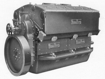
 The first 4-cylinder Paxman-Ricardo engine, developing 11 bhp per cylinder at 1000 rpm, was offered to the market in 1934. Before its introduction Paxman's fastest engine ran at 750 rpm. RQs ran between 1000 and 1500 rpm making them the Company's first high-speed diesels - or, more accurately, what were considered as high-speed for diesels at that time.
During World War 2 large numbers of 4-cylinder RQs were built for generating sets. These were supplied to the War Office for powering searchlights and to the Admiralty for use in landing craft. After the war only the 4-cylinder RQ was offered for sale. A special type of RQ was the 6-cylinder RQE, a fully flameproofed engine supplied to the North British Locomotive Co for their 'Miner' locomotives. The 6RQE was rated at 100 bhp at 1,250 rpm.
Details of surviving examples of the RQ engine have been moved to a new page about the Paxman-Ricardo RQ Engine Range. That page also has additional information on the RQ range.
Main features of the RQ range of engines:
- Bore and Stroke: 4.5/8" x 5.7/8"
- Cylinder configurations: 1, 2, 3, 4, 5, 6 - all in-line. (Only 4-cylinder after 1948)
- Power output: 11 bhp per cylinder at 1,000 rpm, 15 bhp/cyl at 1,500 rpm.
- Other features: Compression ratio 18 : 1. Ricardo Comet Mk III combustion chamber. Naturally aspirated.
- RW
 A larger version of the RQ, a number of RWs were installed in destroyers and corvettes built during World War 2. The 8RW was discontinued in about 1950 following an investigation by John Cove into several camshaft failures. He found the problem was bending caused by the method of machining the cylinder blocks. This resulted in errors which caused the camshaft to flex as it revolved. The cost of improved tooling to eliminate the problem was considered prohibitive, and the planned development of the 4RPH was about to give Paxman a smaller engine of similar horsepower so the decision was made to cease manufacture of the 8RW. Production of other RWs tailed off in 1952, with only the occasional engine being built in the two or three years which followed.
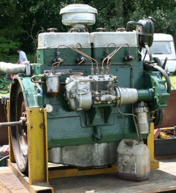
Two HM Customs & Excise 45' launches, 'Hunter' and 'Diligence', were powered by 6RWM engines. A 4RW, in running order, is now in preservation at the Museum of Power, near Maldon, Essex.
- Bore and Stroke: 5½" x 7"
- Cylinder configurations: 4, 5, 6 and 8
- Power output (per cylinder: 20/24/28 bhp at 1,000/1,250/1,500 rpm, (naturally aspirated); supercharging increased output by 25%.
- Other features: compression ratio 17½ : 1; dry cylinder liners; light alloy pistons; Bosch type fuel pump, gear driven from crankshaft; spring loaded pintle-type injectors; air or electric starting; offered in supercharged form with Roots type blower driven from crankshaft by vee belts. It is not known whether any RWs were supplied with a Roots blower but in John Cove's experience no Paxman engine/Roots blower combination was ever successful.
- RX & 6RXS
- The RX was successor to Paxman's VX Heavy Duty Diesel which had been introduced in 1931. Both engines had the same bore, stroke and normal operating speed. The power output of the normally aspirated RX at 600 rpm was little more than that of the VX, 56 bhp compared with 50 bhp per cylinder (normal load). The key difference was the RX's Ricardo Comet Mk III cylinder heads for indirect fuel injection.
Introduced no later than 1937, the RX was built mainly as a 4, 6 or 8 cylinder engine for marine and industrial use, the 5 and 7 cylinder versions being dropped after the start of the War. 6RX engines were installed on board HMS King George V, HMS Edinburgh, and HMS Renown, in 1938, for driving generators. After the War the 6 and 8 cylinder versions became available in supercharged forms.
A specialised verson of the RX was the 6RXS. Designed for service in submarines it had a fabricated steel frame that made it more shock-resistant and lighter than a six-cylinder RX. The 6RXS powered all British 'U' and 'V' Class submarines built during World War 2. Developing 400 bhp at 825 rpm, each engine was coupled to a 275 kW generator to produce power for the diesel-electric propulsion system. RXS engines were made in pairs, left and right handed, so that all the controls were between the two engines. The Bosch fuel pump fed fuel through an injector with a pintle type nozzle with an injection pressure of 1,800 psi. The compression pressure was 530 psi and the maximum firing pressure at full load 760 psi. The governor ran at half engine speed and the overspeed governor was set to cut off fuel at engine speeds above 950 rpm. According to Paxman records a total of 189 6RXS engines was despatched. Details of most of the orders for them are on the page Paxman-Ricardo 6RXS Engines. Information about the 'U' and 'V' Class boats can be found on the Paxman Submarine Engines page.
- Bore and Stroke: 9½" x 12". Swept volume 13.94 litres per cylinder.
- Cylinder configurations: 4, 5, 6, 7 and 8
- Power output (per cylinder): 56/70 bhp at 600/750 rpm (naturally aspirated); 75/93.3 bhp at 600/750 rpm (supercharged).
- Other features of the RX: Cylinder block supported on 'A' frames and secured by long high tensile through bolts to the bedplate which carried the main bearings. This arrangement permitted large inspection doors for removing connecting rods and pistons, etc. Wet cylinder liners; Ricardo 'Comet' head; CAV-Bosch type fuel pump. Compression ratio 15½ : 1. Fuller details can be found on the RZ, RX and RXL Technical Specification page.
- RXK
- Only eight RXK engines were ever built. Basically an RX engine, one key difference was its 13" stroke: an inch longer than that of the RX and RXS. All eight RXKs were ordered by the Air Ministry, London, in 1939: four in May, two in August and two in October. They were 6-cylinder in-line types, with a rating of 283 bhp at 500 rpm. Each was direct coupled to a 150kW AC generator made by ECC (Electric Construction Co of Wolverhampton). One went to RAF Hucknall, Notts (probably), one to RAF Walters Ash and two to nearby RAF Bradenham in Buckinghamshire, two to RAF Newcastle-upon-Tyne, one to RAF Silloth and one to RAF Kirkbride in Cumbria.
By May 1953 the set originally supplied to RAF Silloth, No 50108, was installed in the Royal Naval Hospital, Chatham. In early 2020 this set was still in service as a standby generator at a large glasshouse nursery at Whitchurch, near Ross-on-Wye, owned by Haygrove Ltd. A testament to the quality of the engine that it was still in service 80 years after it was built. The value of the original order for this alternator set was £3,576-15s-6d.
- Bore and Stroke: 9½" x 13"
- Cylinder configuration: 6-cylinder in-line only
- Power output: 283 bhp at 500 rpm.
- RXL
- A long stroke version of the RX, having a 17" stroke instead of the 12" stroke of the RX and RXS. Paxman despatch records show only ten RXL engines having been built: one 3-cylinder, three 4-cylinder, one 7-cylinder and five 8-cylinder types. Two 4-cylinder MRXL ('M' indicating Marine propulsion application) engines were installed in Algerian fishing vessels, each rated 245/270 bhp at 450 rpm. Two 8-cylinder MRXL engines were installed in the MacBrayne ship "Lochiel", built in 1939. These were each rated 440 bhp at 400 rpm. The other six RXLs drove generating sets. The RXL appears to have been dropped from the Paxman range at the start of World War 2.
- Bore and Stroke: 9½" x 17"
- Cylinder configurations: 3, 4, 7 and 8-cylinder in-line.
- Power output (per cylinder): 57.5 bhp at 428 rpm, 60 bhp at 450 rpm.
- Other features: Paxman publicity literature offered marine versions to run at speeds of 300 rpm or higher if required. Only four MRXL engines were built. As noted above, the two 4MRXLs ran at 450 rpm, and the two 8MRXLs at 400 rpm. Compression ratio 15½ : 1. Fuller details can be found on the RZ, RX and RXL Technical Specification page.
- RZ
- Introduced around 1935, the RZ appears to have been successor to the VZ Heavy Duty Diesel, in the same way as the RX was successor to the VX. It differed from the VZ in having Ricardo Comet cylinder heads and a fractionally larger bore. The RZ range appears to have come to an end with the outbreak of War. After the War its power range was covered by the RPH.
The twin screw vessels MY Pomeroon (1936), MY Lady Northcote (1937), and MY Barima (1939), built by Ferguson Brothers of Port Glasgow for the Transport and Harbours Department of British Guiana Railways, were each fitted with two 6 cylinder MRZ main propulsion engines, each producing 180 to 200 bhp at 1,000 rpm. The engines for Barima cost £1,970 each. (These ships also had 47 bhp 3RQ and 53 bhp 4RQ auxiliaries.) The 6RZ was also supplied for rail traction duties, one being installed in a Hunslet eight wheel locomotive for local freight and heavy port shunting duties on the Trinidad Government Railways in 1940.
- Bore and Stroke: 6.7/8" x 10"
- Cylinder configuration: 4, 5, 6, 7, 8 (all in-line)
- Power output: (per cylinder): 31.25 bhp at 750 rpm, 42 bhp at 1,000 rpm.
- Other features: Basic construction similar to the RX with wet liners. CAV-Bosch type fuel pumps. Compression ratio 16½ : 1. Normal speed 750 rpm, but could be adjusted to run at 1,000 rpm. Fuller details can be found on the RZ, RX and RXL Technical Specification page.
- 12 VEE RA
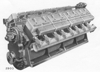
 The Company's earliest 'vee' type engine, the VeeRA made its debut at the Shipping, Engineering, and Machinery Exhibition at Olympia in September 1935 when a 12 cylinder version was put on show. (1) The crankshaft was housed in a separate bedplate along similar lines to the earlier heavy oil engines.
Advertisements featuring the Vee RA appeared in the September 1937 and January 1938 issues of The Motor Ship saying it was manufactured in a range of sizes from 8 to 16 cylinders, developing 220/1,000 bhp at speeds of 1,000/1,750 rpm. An article in the June 1938 issue of The Oil Engine states "The 'RA' type is manufactured in 8, 12, and 16 cylinder models, … " but surviving Paxman records suggest that only one V8 and four V12 engines were built. For whatever reason the VEE RA was quickly superseded by the VEE RB (see next item).
- Bore and Stroke: 6½" x 7½"
- Cylinder configurations: V8, V12. No evidence of a V16 having been built.
- Power output (12 cylinder version): 368 kW (500 bhp) at 1,500 rpm.
- Other features: 60° vee; cylinder blocks cast integrally with upper part of crankcase; cast iron 'dry' type cylinder liners; fork and blade con-rods; individual Ricardo Mk III Comet cylinder heads; compression ratio 15.5 : 1; compression pressure 530 psi; firing pressure 750 psi; BMEP 87.5 psi; single camshaft operating overhead valves on both cylinder banks; CAV-Bosch monobloc fuel pumps; single hole pintle type injectors; standard starting system - compressed air at 350 psi. Main construction was in cast iron and the 12 cylinder engine weighed approximately 7,600 lbs.
- VEE RB
 Introduced in 1937, the VEE RB had a fractionally larger bore and stroke than the VEE RA. A major difference was the use of an underslung crankshaft which substantially reduced its overall weight.
A 16 cylinder version had a two hour rating of 1,000 hp at 1750 rpm, and a continuous rating of 800 hp at 1,500 rpm. Two 16 cylinder Vee RBs were installed in a twin screw experimental high speed craft 'MY Tarret', which set the world diesel yacht speed record in 1938.
Another notable application of the VEE RB was in the Gay Viking class of fast merchantmen which ran the German blockade of the Skagerrak to bring vital ball bearings from Sweden to the UK in the Second World War. The full story is told on the The Blockade Runners page.
- Bore and Stroke: 7" x 7¾". Swept volume 298.3 cu in / 4.89 litres per cylinder.
- Cylinder configurations: V8, V12, V16
- Power output: 265 bhp at 1,000 rpm, 400 bhp at 1,500 rpm (8 cylinder version).
- Other features: 60° vee; fork and blade con-rods; dry type cylinder liners; cylinder heads cast in groups (unlike the VRA); Ricardo Comet Mk III combustion chambers; compression ratio 15.25 : 1; compression pressure 550 psi; firing pressure 800/850 psi; BMEP 87.5 psi; stellited valve faces and seats; CAV-Bosch monobloc fuel injection pump(s); single hole pintle type injectors; thin plate construction sump.
- 12TP and 12TPM
- The 12 cylinder TP engine was derived from the VRB, sharing the same bore and stroke and 60° vee form. Like the VRB it featured fork and blade connecting rods and Ricardo Comet cylinder heads. The 12TP was developed early in World War 2 in response to a demand for large numbers of compact, high power engines for Britain's war effort. The only potentially suitable engines available at the time were petrol, with their attendant high fire risk, particularly when installed in confined spaces in armoured vehicles or naval vessels. In any event the threat to Britain from the air in 1940 led to the RAF receiving priority over the Army and Royal Navy in allocation of the limited number of high performance petrol engines which were available.
The need was for a suitable high speed diesel which could be manufactured in quantity. Paxman's experience with the VRB, an established engine of the desired size and power output, provided a good base from which to start. However the engine block of the VRB, incorporating the crankcase and both banks of cylinder blocks, was a complex single casting and unwieldy for machining on account of its size. Few other engineering concerns would have had the necessary skills and facilities to manufacture it successfully. Standard Works was fully occupied with other war work and had little spare capacity. Paxman's highly effective solution was to redesign the VRB, breaking it down into more manageable elements which were within the manufacturing capabilities of many small sub-contract workshops. The designation TP stood for 'three pieces' referring to the split of the original design into three main parts: the crankcase and two banks of cylinder blocks, or according to another opinion: crankcase, cylinder blocks, and cylinder heads.
From Paxman records we know the first 12TP and a further early one were supplied for prototype heavy tanks built by William Foster of Lincoln. The next call for the TP was to power an exceptionally large trench digging machine, the brainchild of Sir Winston Churchill, the prototype of which was called 'Nellie'. Large numbers of TPs were ordered for this project but few were actually delivered. With the fall of France in the summer of 1940, the trench warfare roles envisaged for both the heavy tank and Nellie disappeared overnight.
After the evacuation of the British Expeditionary Force from Dunkirk in 1940, Edward Paxman was summoned to the Admiralty in Whitehall for urgent talks. Barring Britain's defeat, it was almost inevitable that at some future stage the Navy would be called upon to land substantial British ground forces back onto the beaches of mainland Europe. That would necessitate the building of large numbers of tank landing craft and propulsion engines for them. Edward Paxman returned to Colchester charged with the task of quickly producing plans for a modified 12TP, the 12TPM (the 'M' indicating Marine) suitable for a tank landing craft propulsion unit. His second task was to consider how best to build the engine in the volumes required.
 Production of the 12TPM commenced in 1942. To provide space for additional manufacturing and test facilities, the Ministry of Supply leased the premises of the old Britannia Lathe and Oil Engine Co in Colchester which were in a very poor state having been out of use for a number of years. The works were reconditioned by Paxman which also managed the assembly, test and despatch of TPM engines on behalf of the Ministry.
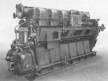
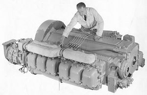
Left: 12TPM engine complete with gearbox
Over 400 engineering concerns, large and small, were enlisted to manufacture the 1,300 or so different components which went into the construction of each engine. These parts flowed into the Britannia Works where the engines were assembled and tested. Britannia Works was hit by incendiary bombs in February 1944, burned out, and rebuilt in five months. During this time TPM production continued at the rate of over 30 engines per week.
12TPM engines powered all the World War 2 British-built diesel-engined tank landing craft which played a major role in the Normandy landings. 3,533 TPMs were built before hostilities ceased: 2,227 by Paxman at Colchester and 1,306 at Renault's British factory at Western Avenue, Park Royal, London W3. It is thought that about an additional 30 or 40 12TP (not TPM) engines were built by Paxman. TP and TPM engines carried five-digit serial numbers. Those of the 12TPs built by Paxman began with a '5' or '6'. Serial Numbers of the 12TPMs built at Colchester began with a '7' and those built at the Renault factory began with an '8'.
The 12TPM was developed to meet a specific wartime need, for which only a relatively short service life was envisaged at the design stage. That philosophy carried over to the production of components where a certain latitude was allowed on manufacturing tolerances provided parts were fit for use. The engine performed well in the duties for which it was originally designed. However, after the war many landing craft were sold off and put to work on regular cargo and ferry services by their new commercial owners. Surplus TPs were also harnessed to a number of other applications for which they were never intended. In these duties the running hours built up to levels never encountered during the war with the result that parts began to wear and fail. All this added to Paxman's experience of high speed diesels in extended peacetime service. Valuable lessons were learned and incorporated in the design of the TP's post-war successors, the RPH ranges of engines.
- Bore and Stroke: 7" x 7¾". Swept volume 298.3 cu in / 4.89 litres per cylinder.
- Cylinder configurations: V12 only.
- Power output: 600 bhp at 1,500 rpm. However the book of Running and Maintenance Instructions gives Speed:- Max. 1,375 rpm, Idling 700/750 rpm. Output 500 bhp at 1,375 rpm.
- Other features: The crankcase was cast separately from the cylinder blocks; 4 blocks, each of 3 cylinders, were arranged in two banks; fitted with dry liners these were hydraulically pressed into the cylinder blocks. Weight of bare engine 61 cwts (just over 3 tons). Fuel consumption .42 lbs per BHP hour. BMEP (full load) 81 lbs/squ inch. Compression ratio 17 : 1.
- RPH (Series 1 and 2)
- Board minutes show that Edward Paxman was planning the RPH in 1942. In Paxman's Service Department there is a record of RPH drawings dated as early as July 1943. From this it is evident that long before the end of the war was in sight the Company was preparing for its post-war future with plans for a high speed 7" bore engine suitable for peacetime applications. Design work on the RPH continued during 1944, as and when demands of war production allowed. A booklet prepared for a visit to Paxman's Works by Ministry of Supply contractors on 23rd June 1945 has a page devoted exclusively to the Paxman RPH range which is stated to be "At present available in 6 and 12 cylinder models". The same page carries a photograph of an in-line 6 cylinder version and notes that the range would shortly include 4 and 8 cylinder models and that "all models may be supercharged as required". At the back of the booklet is a chart giving output ratings for 4, 6, 8, and 12 cylinder RPHs, both naturally aspirated and supercharged, at 1,000, 1,250, and 1,500 rpm respectively. Much of this was probably more a reflection of Paxman's ambitions for its new range than of what the Company was actually producing or capable of delivering at the time. Subsequently the many new challenges and changing circumstances of the immediate post-war period no doubt forced the Company to review which RPH versions should be put into production and the time scales for doing so.
There is no doubt that by 1947 the RPH Series 1 was in volume production. How much earlier production actually commenced remains uncertain. Initially offered as a 12 cylinder engine, the RPH Series 1 was basically a TP with various internal modifications and improvements such as a hardened camshaft. Externally the two engines looked virtually indentical. Next an in-line 6 cylinder version was developed. This was a 12 cylinder engine minus one bank of cylinders, the gap being closed by a plain entablature. Thus the in-line 6 was one bank of cylinders inclined at 30° from the vertical. The connecting rods were the standard forked rods but the bearing block oil holes which normally fed the blade rod bearing were blanked off. These engines were naturally heavier and more expensive than a purpose designed 6 cylinder would have been but, with minimum design effort, Paxman was able to offer a 200 bhp engine using existing parts. There was also the advantage of being able to use scarce bearing blocks which would otherwise have had to be scrapped because of faults in the convex external copper/lead bearing surface which rendered them unsuitable for a 12 cylinder engine.
Later, a V6 Series 1 was introduced for customers wanting a short, compact power unit. 93 were built between 1951 and 1956, of which 53 (39 naturally aspirated, 14 pressure charged) were for rail traction, generally in small industrial shunters. One of the pressure charged V6s formed the basis of Paxman's experimental 'Hi-Dyne', an engine specially adapted to give approximately constant horsepower over a range of engine speeds and designed primarily for rail traction.
Between 1947 and 1954 many hundreds of 6 and 12 cylinder RPH Series 1 engines were produced, in both naturally aspirated and pressure-charged forms. In 1954 alone sixty V12 Series 1 engines were despatched and two were sent out as late as 1958.
A full redesign was necessary before the RPH could shake off its wartime roots and become a more reliable commercial product. All the experience gained with 12TP and Series 1 engines was therefore embodied in the RPH Series 2 which became a robust engine providing reliable service in many applications including oil well drilling, electrical power generation, and rail traction.
The RPH Series 2 engine was introduced in 1951. Among the most important changes were greatly improved accessibility for maintenance and repair, increased bearing areas, gear driven water pumps, and roller cam followers in place of the previous slipper followers. The Series 2 featured a stiffer crankshaft with an additional bearing at the drive end to take the weight of a single bearing generator or similar close coupled driven machinery. The bearing blocks were redesigned for the larger crankshaft and provided with thin wall shell bearings instead of the cast-on copper/lead used on the TP and Series 1. The blade rod also carried its own shell bearing and the convex surface of the bearing block was plated with hard chrome to provide a hard wearing bearing surface. Manufacture of the blocks and chrome plating them was done in-house at Paxman's own works to ensure close quality control.
The Series 2 engines had a chain driven camshaft instead of the gear driven camshaft of the Series 1. The latter had proved unreliable as ball bearings used in the arrangement became worn and balls fell out into other parts of the engine. A further small but significant difference between the two engine ranges was that bolts and studs on the Series 1 had BSF threads whereas those on the Series 2 were UNF.
Initially the Series 2 was produced in V12 and V16 versions, both naturally aspirated and pressure-charged. The 16 cylinder engine was withdrawn in 1961 by which time the YH range, with the same 7" bore, was well established and able to offer the higher powers.
By 1954 V4, V6, and V8 versions of the Series II had appeared. Originally available only in naturally aspirated form, there were significant differences between these engines and the V12. The latter had its camshaft in a separate cambox and individual cylinder heads. The smaller engines had their camshafts fitted within the crankcase and had multi-unit cylinder heads. These engines also had gear driven balance shafts in the crankcase in various combinations to eliminate primary and secondary unbalanced forces and couples, which varied according to the number of cylinders.
1958 saw the introduction of the RPH Mark 3 and Mark 4. Both featured Alfin pistons, hardened valves and seats, and other small modifications. Up to this time all RPH engines, including Series 1, were designed for a maximum continuous speed of 1,250 rpm. Mark 4 and later versions were designed for a maximum continuous speed of 1,500 rpm.
The Paxman Sales Engineers' Handbook (issued c.1967/68) describes Mark 5 versions as pressure charged, using Holset air cooled turbo-blowers, and having oil cooled pistons, larger fuel pump plungers, and modified inlet and exhaust manifolds. It goes on to say production of the Mark 5 versions of the 4, 6, and 8 cylinder types started in 1960, while records show the first despatches of each of these types occurring in 1961. Production of the Mark 5 and 6 (pressure charged) V12 commenced in 1961. A history of the changes to technical specifications and details of the differences between the various 'Marks' can be found on the page RPH and YH Engine Versions.
The RPH continued in production into the 1980s and a total of over 6,690 RPHs were made, many of which are still in service.
- Bore and Stroke: 7" x 7¾". Swept volume 298.3 cu in / 4.89 litres per cylinder.
- Cylinder configurations:
Series 1: in-line 6, V6, V12
Series 2 onwards: V4, V6, V8, V12, and V16 - Power output: (c. 1967)
12RPH: 500 bhp at 1,250 rpm (naturally aspirated)
12RPHX: 600 bhp at 1,250 rpm (turbocharged)
12RPHC: 680 bhp at 1,250 rpm (turbocharged and intercooled) - Other features: 60° vee; 2 valve Ricardo Comet cylinder heads. Compression ratio 17.25 : 1 .
- RPL
 The RPL was developed from the RX, having the same bore and stroke. Initially offered as a range of vertical in-line engines, it later appeared in V12 and V16 forms with fabricated steel frames.
One large order was for 120 four-cylinder RPLs for a Tin Mine Rehabilitation project in Malaya. The engines were supplied for driving pumps in Malayan tin mines which had been seized by the Japanese during World War 2. The last 4RPL built for this contract was completed in spring 1949. (2) RPLs were sold to mining companies in various parts of the world including Malaya and Australia but it has been said that price was a problem in Australia. The RPL range remained in production up to the early 1950s. Some of the earliest vee form RPLs powered two diesel-electric grab hopper dredgers, 'Mersey 26' (1948) and 'Mersey 27' (1949), built by Ferguson Brothers of Port Glasgow for the Mersey Docks and Harbour Board. Each vessel was fitted with three pressure-charged 12RPLs, each engine developing 780 bhp at 520 rpm. A rail ferry ship for the Harwich-Zeebrugge route, 'Norfolk Ferry', which was launched and entered service in 1951, was equipped with three 4RPL auxiliaries, each driving a 125 kW Bruce-Peebles 220V generator at 650 rpm.
John Cove, who had close personal involvement in failure investigation, service and quality while at Paxman, recalls that some RPL engines did suffer from cracking of the cylinder liners under the top flange. There was some difficulty with the machining of the housing which led to lack of concentricity between the flange recess and the housing at the bottom of the liner which carried the sealing rings. This highlighted the need for proper tooling to eliminate the problem but on engines already in service improvement was obtained by larger radii under the liner flanges.
A 12 cylinder version was built with pressure-charging by a Roots-type blower, gear driven from the crankshaft. John Cove well remembers one such engine which caused a lot of trouble on test. An attempt was made to test it at night to catch up on delivery but the blower made such a noise that Paxman received complaints from residents as far away as the High Street. Apart from excessive noise, the main problem was that the inertia of the blower rotors was such that the rapid acceleration at starting imposed enormous loads on the gears and shaft driving the blower, causing repeated failures. Flexible couplings were tried but quickly disintegrated. John believes the Company finally had to go back to the customer and persuade him to accept it as a normally aspirated engine at a somewhat lower rating. He says Roots blowers were never tried again after that!
- Bore and Stroke: 9½" x 12"
- Cylinder configurations: 4, 5, 6 and 8 in-line; V12 and V16 (45° vee)
- Power output (per cylinder): Naturally aspirated: 56 bhp at 600 rpm, 70 bhp at 750 rpm, except the 4 cylinder version (56 bhp at 600 rpm, 60.75 bhp at 650 rpm). Pressure-charged (6 and 8RPLX): 75 bhp at 600 rpm, 88.6 bhp at 750 rpm.
- Other features: The in-line RPLs had the same basic construction as the early Paxman monobloc engines - a cylinder block supported on 'A' frames and secured by long high tensile through bolts to the bedplate which carried the main bearings. This arrangement allowed large crankcase doors so connecting rods and pistons, etc., could be replaced without removing cylinder heads or other components. Fitted with Ricardo 'Comet' cylinder heads (i.e. indirect injection), block fuel pumps, and single hole pintle type fuel injectors. Compressed air starting. Engine speeds of 600 or 750 rpm, except the 4 cylinder versions which ran at 600 or 650 rpm. Pressure-charged in-line versions were offered with single stage centrifugal blowers driven by exhaust gas turbines but there is some question as to how many, if any, were actually made. The bare 16RPL weighed 14 tons.
Fuller details can be found on the RPL Technical Specification page.
- YE
- Those who previously have come across the YE might think it a Ruston engine. However, Ray Roxby told me it was designed and developed by Paxman at Colchester in the late 1940s and that when it was ready for production Paxman's associate company Ruston decided to transfer manufacture of the YE to Lincoln and to market it under the Ruston name. He adds that part of the deal was that Paxman would be allowed to build a hundred engines before the transfer took place. An article in the June 1951 issue of Diesel Railway Traction is headed 'Ruston's New Engine' and goes on to describe 'A new range of four stroke oil engine known as the YE, and covering 4, 5, and 6 cylinder engines … has been introduced by Ruston & Hornsby, Lincoln for a variety of duties including small locomotive applications'. The 6YE appears in a Paxman oilfield engine catalogue of April 1951, and at least some 4YEs were ordered by Ruston-Bucyrus in 1951.
- Bore and Stroke: 5" x 5.7/8"
- Cylinder configuration: 4 and 6 in-line.
- Power output (6 cyl - continuous): 98 bhp (normally aspirated), 137 bhp (pressure charged) at 1,500 rpm.
- Other features: Cast-iron crankcase and cylinder block. Underslung crankshaft, copper/lead main bearings, block fuel pump.
- RPA
- In May 1942 Edward Paxman notified the Board of his plans for a proposed RPA engine. Records indicate this was to be a four-stroke single cylinder engine, of 3½" bore x 4.1/8" stroke, of which four might be made. As yet it has not been possible to find out how many of these prototypes were actually built. Don Meiklejohn has searched Paxman's film record of contract files and can find no record of any RPA engines being despatched to customers.
- Bore and Stroke: 3½" x 4.1/8"
- Cylinder configurations: single cylinder.
- RPB
- Proposals to design and build the RPB were discussed with the Directors in November 1942. At the time the RPB was planned to have the same bore and stroke as the RPA. There are surviving Paxman records of two RPB engines being built for 'customers'. Orders 4364 and 4365 (i.e. Paxman contract numbers) were entered on 20th October 1943 and were for Ruston & Hornsby (which held the controlling interest in the Paxman business) but no destination or purpose is recorded. It is not known whether they were being sent to Ruston to carry out more development running or whether Ruston had customer orders for them. Order No 4364 was for a single cylinder engine rated at 4 bhp at 1,000 rpm but the speed is given as 1,000 / 1,500 / 1,750 rpm. No 4365 was for a twin cylinder engine rated at 8 bhp at 1,000 rpm with the same speeds. Both were listed as 'hand started' and were to be supplied with a conversion kit for direct injection. The bore and stroke were quoted as 3½" x 4.1/8" - the same as the RPA. Other (later?) RPBs are believed to be 3¾" bore x 4½" stroke.
 It would appear that only six RPB engines were built: the two described above and four 4-cylinder types. Either the single cylinder or twin cylinder engine went to a West Bergholt farmer to drive a fodder mill. One of the 4RPBs was installed in a mobile crane used on the Paxman site. By the end of 1965 this had given 16 years service. Two were installed in tractors, one belonging to Mr J R Bergne-Coupland, Ruston's Assistant Managing Director and the other to a Mr Fielden, brother of Ruston's Engineering Director. The fourth 4RPB was fitted in the chassis of a 1924 Rolls-Royce Silver Ghost which was used by its owner, Mr Austin Farrar, for towing his motor launch. (3) This car was sold at auction by Christie's at Beaulieu in September 1994 for £11,500. After he had acquired a Rolls-Royce engine for the car, the new owner sold the 4RPB in 1998 to the late Alex Walford of Colchester.
Right: The 37 bhp 4-cylinder RPB engine of 1949 now at the Museum of Power, Langford.
RPB engines were relatively heavy for their power output, the four cylinder type weighing 12 cwt. Among Paxman's development records are 4RPB performance graphs dated December 1944. It is thought that the 4RPBs, other than the development engine, were built in the late 1940s. The 4RPB No 700154/4, originally installed in the 1924 Rolls Royce, has survived and as at 2015 is at the Museum of Power at Langford, near Maldon in Essex. It was probably built in 1947/48 and left the factory in 1949. Rated 37 bhp at 1,700 rpm, the engine is still in very good running order. Apart from modification of the governing arrangement, little restoration work was necessary.
The RPB was intended as a prime mover for tractors, perhaps hoping to cash in on the market exploited so successfully by Frank Perkins of Peterborough. As will be seen from the above, the RPB never really got beyond the development stage and limited field trials.
- Bore and Stroke: initially 3½" x 4.1/8"; later RPBs, such as Alex Walford's, believed to be 3¾" x 4½"
- Cylinder configurations: 1, 2, 4 in-line.
- Power output (4 cylinder version): 37 bhp at 1,700 rpm.
- Other features: Ricardo whirlpool combustion chamber, instead of the Comet chamber used on all other Paxman indirect injection engines.
Direct Injection
In the ongoing quest for ever higher power output the advantages of indirect injection were outweighed by some of the limitations it imposed. Indirect injection engines are not well suited to turbocharging or high speed operation, they are less fuel efficient, and can be harder to start at low temperatures. One particular disadvantage of indirect injection was that the heat of combustion was not evenly distributed over the piston head. The resulting hot spot at the side of the piston opposite the precombustion chamber meant that the piston expanded unevenly and therefore had to be machined into a kind of oval shape when cold to approximate to a cylindrical shape when hot. Furthermore the hottest spot on the piston determined the point at which the oil film began to break down and thus limited the maximum possible rating. An engine with the Comet system, which would typically be rated at about 88.5 psi bmep in normally aspirated form, could therefore only be pressure charged to a very small extent before reaching a temperature limit on the hottest spot on the piston. A direct injection combustion system heats the piston evenly all round and is thus capable of accepting a much higher level of pressure charging before the whole piston reached the limiting temperature. This was a major factor in Paxman's decision to develop its directly injected 7" bore YH engine, successor to the RPH series, and the YL as the successor to the RPL. The chief difficulty Paxman faced in its early experience of direct injection was trying to achieve a clear exhaust under full load conditions. Over the years considerable research and development effort was expended in seeking to overcome the problem.
Paxman Direct Injection Engines
- YH
- Based on the RPH and introduced in 1952, the YH was the first Paxman high speed engine with direct injection. Initially built as an aluminium alloy engine to Admiralty specifications, the YHA became classified as an ASR (Admiralty Standard Range) 2 engine for 15 years (until superseded by the Ventura). To meet Admiralty demand for large numbers of these engines, the work was for a time shared between Paxman, Ruston, and Ransomes Sims & Jefferies. A special organisation, APRRO (Admiralty - Paxman - Ruston - Ransomes - Organisation), was set up to handle the contracts. Between 1953 and 1955 a total of 418 of the 12 cylinder YHA were built: 205 by Paxman, 120 by Ruston, and 93 by Ransomes. During this period Paxman also produced 25 of the 6 cylinder version.
The YHA's aluminium construction permitted a low magnetic signature and its initial application was in minesweepers. These vessels had two engines for propulsion and a third for the pulse generator. The latter was driven via a flywheel weighing about 2 tons, made from a solid aluminium bronze casting. The inertia of the flywheel was so great that for starting purposes a slipping centrifugal clutch had to be interposed. This had to be a special design which would disengage on overrrun as otherwise, once engaged, it would be impossible to decouple until engine, flywheel and generator had almost come to rest which would take a very long time. Some of the flywheel castings were rejected after machining because of visible external defects which caused Paxman's quality engineering staff to wonder whether any might contain hidden internal defects. Since failure of one of these flywheels in service could have sunk the vessel, they were all subjected to an overspeed test in a quarry-like pit on the boundary of Standard Works, well away from everything else. The flywheels were mounted on a short shaft between two bearings and each powered up to 1,500 rpm with an electric motor for about 30 minutes, while everyone kept well clear! None failed the test but it took each flywheel nearly an hour to come to rest when the current was cut off. The pulse generating sets were mounted on welded aluminium underbases which gave Paxman unrivalled experience in the welding of thick aluminium sections. No one in the UK had previously been successful in attempting such work. Jim Edwards, Paxman's welding expert, was the key person responsible for overseeing the introduction of new technology for the task and overcoming initial problems. This pioneering work enabled Paxman's Boiler Division to add the manufacture of specialist stainless steel fabrications to its range of work.
In addition to minesweepers, YHA engines were also installed as auxiliaries in Leander Class frigates built for the Royal Navy and a number of overseas navies. Each of the four Resolution Class (Polaris) submarines, HMS Resolution, Renown, Repulse and Revenge, had two A12YHAZ engines for auxiliary power, driving Laurence Scott generators. These particular engines were naturally aspirated with a rating of 290 kWb at 1,200 rpm, a normal load output of 422 bhp and a maximum output of 464 bhp.
A surviving example of a 12-cylinder YHA engine, in working order, is now in the core collection of the Internal Fire Museum of Power in West Wales. Acquired from Chatham Dockyard in 2011, it is part of a Paxman-built skid-mounted 150kW alternator set despatched to the Admiralty in 1957.
Commercial versions of the YH engine, the YHX, of cast iron construction and pressure-charged, were introduced in 1954.
- Bore and Stroke: 7" x 7¾". Swept volume 298.3 cu in / 4.89 litres per cylinder.
- Cylinder configurations:V6, V12 and V16
- Maximum Power Ratings:
12YHX: 750 bhp at 1,250 rpm; 900 bhp at 1,500 rpm (turbocharged)
12YHC: 800 bhp at 1,250 rpm; 950 bhp at 1,500 rpm (turbocharged and intercooled). - Other features: Four valve direct injection cylinder heads. Compression ratio 14.25 : 1. Injection pressure 3,000 psi. Fork and blade connecting rods.
- YL
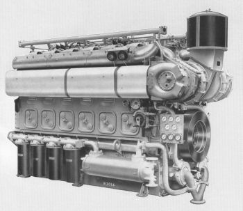 The YL, specifically designed for pressure charging, was the direct injection successor to the RX and RPL ranges. A 12 cylinder prototype was completed in the summer of 1950 for development testing. The YL series was introduced and exhibited at Colchester in May and June 1951. (4) Apart from one 8YLX depatched to Westland Aircraft at Yeovil in 1953, production of the YL really commenced in 1954. An intercooled version of the YLX, the YLC, was introduced in 1955. The additional advantages of intercooling quickly became apparent and after a short while only the pressure charged and intercooled version was offered.
As well as being built in Colchester, a number YLs were made under licence in France and Italy. By the end of 1966 a total of fourteen YLs, in 8, 12 and 16 cylinder sizes, had been assembled in France by Forges et Chantiers de la Méditerranée SA at Le Havre (probably using parts supplied by Colchester). In Italy more than forty 12-cylinder YLs were built by Fabbrica Automobili Isotta Fraschini e Motori Breda, for rail traction. Breda incorporated certain design modifications of their own, including an underslung crankshaft.
Paxman staff who had dealings with the YL speak highly of it and say it proved a very reliable engine in service. The late Denis Turner considered it one of the best engines ever made by Paxman. Although designed to run at speeds of up to 900 rpm (later 1,000 rpm), Denis commented that the engine was happier running at 700 to 750 rpm.
Despite its excellent reputation, the YL did not survive long after the English Electric takeover in 1966 because it competed with the well-established English Electric SV, CSV and RK series. The RK was later built by Ruston at Vulcan Works, Newton-le-Willows, Lancashire.
Details of sales of YL engines, including customers and applications, can be found on the page Paxman YL Engines.
- Bore and Stroke: 9¾" x 10½". Swept volume 784 cu in / 12.85 litres per cylinder.
- Cylinder configurations: V8, V12, and V16
- Maximum Power Ratings:
12YLC: 1,500 bhp at 750 rpm; 1,700 bhp at 900 rpm (turbocharged and intercooled). - Other features: fabricated steel cylinder housing and bedplate; Fork & blade con-rods; 45° vee; 4 valve direct injection cylinder head; individual fuel pumps for each cylinder; pressure-charged and intercooled, viscous torsional vibration damper fitted at free end. Compression ratios: YL 15 : 1, YLX and YLC 12.8 : 1. Designed to run at speeds between 400 (or 600?) and 1,000 rpm. Idle speed between 200 and 300 rpm.
- YM
- Conceived as an uprated version of the YL, the initial design requirement was to obtain a 35% increase in power compared with the existing YL range, making as much use as possible of existing YL parts and tools. As design progressed, the range was projected to cover a power range of 1,000 to 3,000 bhp (continuous) in V8, V12 and V16 versions running at speeds up to 1,000 rpm. It was envisaged that with further development the continuous rating could be extended to 4,000 bhp, a final target which represented a 75% increase in power compared with the existing YL range, achieved within virtually the same space.
The first design followed YL practice with the crankshaft mounted in a bedplate, although a design for incorporating an underslung crankshaft was schemed. Only one YM was built, a V8 development engine. Test Report No 1, dated 18th October 1963, states: 'The engine was largely designed in 1959, but due to policy decisions and production hold-ups development work was delayed, and the prototype 8YMC engine first ran in February, 1963.' The test performance of this engine was reported to compare, in general, favourably with the YL under all conditions. Development work on the YM had ceased by July 1964. Apparently the engine could never have competed successfully with the English Electric RK series, a factor which led eventually to the project being shelved.
- Bore and Stroke: 10½" x 12"
- Cylinder configuration: V8 (a single development engine)
- Other features: 45° vee; fabricated engine housing and separate bedplate; fork and blade connecting rods; four valve cylinder head with central injector; fuel pumps mounted in the vee, air and exhaust manifolds outside the vee.
- ZH
 Introduced in 1954, this was a horizontal or 'flat' 6 in-line cylinder engine. Evolved from the YH, it was essentially half (i.e. one bank) of a Vee 12 YH. The ZH was designed for British Railways primarily as an under-floor mounted power unit for railcars. Paxman was unsuccessful in persuading BR to adopt the engine for this application but large numbers of the pressure-charged version were supplied for the Class 17 'Clayton' Type 1 diesel-electric locomotive used mainly in the Scottish Region.
The engines initially supplied to British Railways were of aluminium alloy construction. Cracking of the castings became a major problem and the engines were rebuilt by Paxman with cast-iron crankcases at great cost to the Company. John Cove, who worked for Paxman at the time, has told me that British Railways had previously tested the first pair of engines with aluminium crankcases before placing an order for a quantity. By that time Paxman had had some experiences with aluminium castings on the YHA and possibly also the YGA air-cooled engine. Both types had experienced troubles with threads and failures in cast aluminium. John went on to say: "Consequently we suggested to BR that we supply the engines with cast iron crankcases from the start but BR were quite adamant that they wanted the engines to be exactly the same as the ones they had tested and which had given no trouble. We were so keen to get the order that we failed to stand up for what we believed was necessary and so supplied them in aluminium. But before long these engines in service had run longer hours than the test engines and troubles began to become apparent and we had to change all the crankcases to iron. The troubles then ceased but this would have been unnecessary if we had taken a stronger line before the order was placed."
- Bore and Stroke: 7" x 7¾". Swept volume 298.3 cu in / 4.89 litres per cylinder.
- Cylinder configurations: in-line 6
- Power output: 300 bhp (naturally aspirated) or 450 bhp (pressure-charged) at 1,500 rpm.
- Other features: aluminium or cast iron main castings; four valve direct injection cylinder heads. Compression ratios: 15.2 : 1 (naturally aspirated), 12.4 : 1 (pressure charged). Injection pressure 3,000 psi.
- YGA (also known as the Vega, not to be confused with the Vega launched in 1986)
 Paxman's only air-cooled diesel. The Company started investigating the feasability of developing a large air-cooled engine around 1953/54. Design of the YGA was apparently mainly the work of Václav Laciny and Roy Goodridge. It is believed that Mr Laciny had worked on air-cooled engines with the Tatra company in his native Czechoslovakia before coming to England. A single cylinder test unit first ran in January 1957, and an eight cylinder development engine in June 1958. Three different designs of cylinder heads and barrels were produced before the final design evolved. Details of the engine were released in 1959 with plans to commence deliveries early the following year. A running example was exhibited at the World Oil Fair, Tulsa, Oklahoma, in 1959. The engine was also put on show at the German Industries Fair, Hanover, in May 1960. It was the largest industrial air-cooled diesel then available.
The individual cylinder heads and barrels were one piece aluminium alloy castings with hardened and tempered cast iron cylinder liners shrunk in. The 1959 publicity literature promoted this engine as being suitable for a wide variety of applications such as rail traction, oil drilling equipment, power generation and driving pumps and compressors. One of its obvious advantages was dispensing with the need for water or oil cooling radiators. The earlier models had a problem with barrels cracking at the lower flange where they were bolted to the crankcase. This was resolved by using long studs which extended through to the cylinder head. Production of the engine was discontinued not long after because the problem of noise proved to be insoluble. To cool a 12 cylinder engine, while keeping it sufficiently compact, the fan had to run at high speed and consumed about 60 hp. The high pitched noise it produced was amplified by all the fins on the cylinders and the air ducting that surrounded the engine. The resulting sound was like a jet engine, making the YGA unacceptable for most applications.
Two 12YGAs, driving 200kW alternators, were supplied for emergency power generation on the P & O liner Canberra (launched 16 May 1960). The ship had to rely on the stand-by sets for propulsion during its maiden voyage when a major fire in the engine room disabled the main generators. An 8YGA was trialed in a Ruston-Bucyrus excavator. Another 8YGA, rated at 220 bhp was installed in a tanker barge, "MV Weasdale H", built by John Harker of Knottingley and launched in 1960. In this the engine was for main propulsion with belt drive between the engine and propeller shaft. Some NATO portable generators, suitable for airlifting, were driven by YGAs.
A 12 cylinder YGA was installed at Ffestiniog Power Station in North Wales to drive the emergency stand-by generator. The power station, commissioned in 1963, was the UK's first pumped storage hydro-electric facility. The engine has been removed from Ffestiniog and taken into preservation at the Internal Fire Museum of Power at Tan-y-groes, West Wales where it arrived on 2nd February 2005. Built in 1960, it remains in very good order and has only run for an estimated 200 hours. The engine was run for the first time at the museum on a crankup day held there on 12th October 2008. It was run about half-a-dozen times under the watchful eye of Alex Walford and ran well, being taken up to 1,500 rpm.
For the last ten years of its active service, a 12YGA originally supplied to the East Worcestershire Waterworks was used to drive an Automatic Mains Failure generator at Freemans of Newent's poultry processing plant in Gloucestershire. When decommissioned in 2009, Freemans generously donated the engine and its MacFarlane generator to the Anson Engine Museum at Poynton, Cheshire. At Newent the engine had been run every couple of months and when retired was still in good working order after 1,400 hours running. It arrived at the Anson on Monday 25th September 2009, complete with its original control panel and special tools, some of the latter still in their original protective wrapping. Thanks are due to Freemans of Newent for agreeing to donate the engine to the Anson so that it could pass into preservation.
- Bore and Stroke: 6" x 6.6"
- Cylinder configurations: in-line 6, V8 and V12
- Power output: (at 2,100 rpm) 6YGA = 233 bhp; 8YGA = 310 bhp; 12YGA = 466 bhp.
- Other features: sphereoidal graphite-iron cast crankcase; 90 degree Vee; side by side connecting rods on Vee-form engines; axial flow cooling fan, chain driven from crankshaft at free end; one inlet/one exhaust push rod operated valve per cylinder; block-type CAV fuel pump; compression ratio 15:1.
- YGX
 Having the same bore and stroke as the YGA, the YGX was a water cooled, four stroke, direct injection, turbocharged engine. A chart dated February 1965 gives ratings for 4, 6, 8 and 12 cylinder versions of this engine in normally aspirated, turbocharged, and turbocharged + intercooled forms. These may have been mainly predictive engineering calculations as it is open to question whether any YGXs were made other than one 4 cylinder and a small number of 6 cylinder in-line engines.
John Cove was at Paxman during the early design stage when there was considerable controversy about whether the YGX should have a maximum speed of 1,500 or 1,800 rpm. The 1,500 rpm school of thought was led by Dr Ron Hughes who had moved recently from Ruston to become Paxman's Engineering Director. He argued that the development costs for the higher speed would be much greater and that moreover there were currently no generators available to take that amount of power at 1,800 rpm. Those who had been longer at Paxman were advocates of 1,800 rpm. They felt that as the Company already had 1,500 rpm engines, they should look to the future and remain at the cutting edge of engine design. In the end it was decided to go for 1,800 rpm and a prototype was built and tested. John Cove thinks this engine must be regarded as an interim and experimental design from which knowledge was gained that was put to good use in other later designs of engine running at 1,800 rpm and even higher. There is documentation quoting a rating at 2,000 rpm but John says this was not part of the design specification during his time at Paxman. He recalls the first prototype was certainly not designed with such a speed in mind; indeed there was quite a struggle to get 1,800 rpm accepted.
- Bore and Stroke: 6" x 6.6"
- Cylinder configurations: vertical in-line 4 and 6
- Power output: 430 bhp at 2,000 rpm.
- Other features: cast iron monobloc engine housing; wet type cylinder liners; cast iron cylinder heads; air-cooled Holset turbo-blower; monobloc fuel injection pump.
- VENTURA (also known as the YJ)
 The design of the Ventura was initiated by Geoffrey Bone not long after he was appointed Managing Director of Paxman. The move was prompted by the need to offer an engine of higher output than the YH, capable of competing against the products of continental engine builders such as Maybach and MAN of Germany and MGO of France. Geoffrey Bone was keen to progress the development of the engine quickly as he saw an opportunity of persuading British Rail to trial it. At the time British Rail were experiencing major problems with some German engines but Paxman had no suitable alternative in its range.
The design of the Ventura was mainly the work of a small team of three men, W R (Roy) Dingle, A C E (Arthur) Hammond, and R F (Ray) Roxby. Roy Dingle, who led the team, had joined Paxman as a student apprentice and progressed by way of the Experimental Department to become Chief Development Engineer, then Chief Design & Development Engineer. Although Geoffrey Bone and A G (Albert) Howe, Engineering Director were both very supportive, Roy recalls that he and his two colleagues were, for the most part, left to get on with the work. He also remembers that design and development were done in a remarkably short time, with the first development Ventura running only 12 to 18 months after starting on the design.
The design of the Ventura commenced with virtually a clean sheet of paper. It marked a major break away from the familiar Paxman 7" bore high speed engine whose pedigree could be clearly traced from the YH, back through the RPH and wartime TP, to the VRB introduced in 1937. These had all been 7" bore and 7¾" stroke compared with the Ventura's wider 7¾" bore and longer 8½" stroke. The Ventura put 34% more swept volume into the YH space envelope to achieve a 50% increase in power.
Test running of the first version of the Ventura, referred to by Development staff as the YJ1, commenced in August 1958, leading on to the engine's launch in 1960. Other than the development prototype, only two YJ1 engines were built. These were 12 cylinder YJXL field trial engines which were installed in the Western Region diesel-hydraulic locomotive 'Majestic' (D830). Experience gained from trial running in 'Majestic' revealed a need to increase the width of the crankshaft's bearing areas. To meet this need the crankcase, as well as the crankshaft, was redesigned resulting in a slightly longer engine, the YJ2. All subsequent Venturas were basically the YJ2 design, generally referred to as the YJ. By 1963 the Ventura was in full production in the four different cylinder configurations detailed below. The British Royal Navy was an important customer for the Ventura which was adopted as the Admiralty's ASR2 Standard Range engine in place of the YH engine. Three Hydrographic survey vessels HMS Hecate, HMS Hydra and HMS Hecla, were each equipped with three 12 cylinder Venturas for their diesel-electric main propulsion and two 6 cylinder Venturas driving auxiliary gensets. Early Type 22 Frigates each had four 16 cylinder Venturas for electrical power generation (12 cylinder Valentas were used for the Batch 3 Type 22s). Fifty one 16 cylinder Venturas were supplied for Attack Class patrol boats of the Royal Australian Navy (two per boat). Another important and very successful application was rail traction, details of which appear on the Diesel Rail Traction page. Additional information on sales and applications of YJ engines can be found on the Ventura page.
- Bore and Stroke: 7¾" (197mm) x 8½" (216mm). Swept volume 401 cubic inches, 6.57 litres per cylinder.
- Cylinder configurations: V6, V8, V12, and V16
- Maximum Power Ratings of final versions:
12YJX: 1,250 bhp at 1,500 rpm (turbocharged)
12YJC: 1,500 bhp at 1,500 rpm (turbocharged and intercooled). - Other features: 60° vee; frame fabricated using high tensile steel plate and steel castings; four valve (two inlet/two exhaust) cylinder heads; compression ratio 13:1 ; direct injection; fork and blade connecting rods; monobloc CAV fuel injection pump on each bank (two on each bank on the 16 cylinder engine shown here); fuel injection pressure 11,500 psi; maximum firing pressure 1,500 psi/103 bar; built in turbocharged (YJX) and turbocharged + intercooled (YJC) versions.
- VALENTA (also known as the Y3J and the RP200)
 About 1965 design work commenced on what was originally conceived as the Mark 3 Ventura, hence the engine's Y3J designation. It had the same bore and stroke as its predecessor but in due course the design changes became sufficiently major to warrant a new name, the Valenta. The people mainly responsible for designing the new engine were Roy Dingle, Morriss Clover, Arthur Hammond and Ray Roxby, although others also contributed. In 1963 Morriss Clover had been appointed Chief Design Engineer (Project Engines). About the time work commenced on the Valenta Dr R V (Ron) Hughes succeeded Albert Howe as Technical Director. As with the design of the Ventura, the Directors were very supportive but did not get closely involved with the detail, leaving Roy and his colleagues to get on with the project. It is worth noting that three of the design team were largely responsible for the design of two of the Company's top of the range, 'flagship' engines. Taken together, the Ventura and Valenta ranges were of major importance to Paxman's diesel business for thirty five years or more. Roy Dingle, with overall responsibility for the design, became the Company's Chief Engineer, a post filled by Morriss Clover when Roy retired. The four Valenta designers mentioned here accrued between them just short of 190 years of Paxman service by the time they had all retired.
The reasons for developing the Valenta were familiar Paxman ones. Customers continued to push for ever higher power outputs without any increase in engine size while the Company remained keen to stay at the cutting edge of large high speed diesel technology. One of the most significant differences between the Valenta and its predecessor is the fuelling arrangement. To achieve the desired increase in power necessitated a higher rate of fuelling than could be delivered by the monobloc type of fuel pump previously used. The decision was made to go for individual fuel pumps for each cylinder which resulted in other big design changes. Instead of the Ventura's one camshaft, the Valenta has three. One is located in the vee between the cylinder banks, to drive the valve gear, and one on the outer side of each cylinder bank to drive the fuel pumps for that bank. Another substantial difference between the two engines is the exhaust system. The Ventura has a relatively conventional arrangement, whereas the Valenta has a water-cooled monobloc design which was easier to manufacture. An estimated three-quarters of all Valentas, but no 6 cylinder in-line types, were built with fabricated crankcases. The Royal Navy in particular preferred this type of construction because of its greater shock resistance and lighter weight. Engines supplied for rail traction also had fabricated crankcases. As a lower cost alternative the engine was offered with a cast SG iron crankcase.
Test running of the Valenta commenced in 1970 and its introduction was announced in the press in early 1971. In due course the Valenta was produced in vee 8, 12, 16 and 18 cylinder versions.
A 6-cylinder in-line version, the 6RP200CL, was designed specifically for a British Rail prototype Class 210 Diesel-Electric Multiple Unit (DEMU) power coach. One of these engines was installed in a prototype Class 210 four-car train set but the class never went into production. However, 6-cylinder in-line Valentas are in service in Royal Navy Sandown Class MCMVs (minesweepers) and similar vessels.
The 12 cylinder Valenta powered all the HST (High Speed Train or Intercity 125) power cars until the introduction of the VP185. Another important application of the 12 cylinder engine is the Royal Navy Type 23 Frigate power module which produces 1.3 MW, 60 Hz at 1200 rpm. The modules themselves, as well as the engines, were built at Colchester and there are four per ship. Two 16 cylinder Valentas power each of the four Upholder Class submarines originally built for the Royal Navy and now in service with the Canadian Navy.
The 37 class A and B Island Class patrol boats of the United States Coastguard Service are each powered by a pair of 16 cylinder Valentas. Four 3,350 bhp 16 cylinder engines power each of the United States Navy's Cyclone Class Patrol Boat Coastal craft. These 52 metre vessels have a design speed of more than 30 knots.
- Bore and Stroke: 7¾" (197mm) x 8½" (216mm). Swept volume 6.58 litres per cylinder.
- Cylinder configurations: V8, V12, V16, V18, and 6 in-line.
- Maximum Power Ratings:
12 cylinder: 2,300 kWb (3,083 bhp) at 1,640 rpm = 257 bhp per cylinder.
18 cylinder: 3,450 kWb (4,625 bhp) at 1,640 rpm. - Other features: 60° vee; single unit Lucas Bryce fuel injection pumps operated by a camshaft on each bank; fuel injection pressure 15,000 psi; maximum firing pressure 2,000 psi/138 bar; single unit cast iron cylinder heads with 4 valves per cylinder - two inlet/two exhaust; fork and blade construction connecting rods (to minimise engine length); dry weights: 12 cylinder 8.12 tonnes, 18 cylinder 11.15 tonnes. Fuller details can be found on the Valenta Technical Specification page.
- VECTARA (also known as the YK or RP180)
 Design of the YK, the first Paxman engine built to metric standards, commenced in October 1968. Parts for prototypes were manufactured in 1972-73 and build of the first prototype commenced in 1973. Development work on the 6 cylinder (in-line) version started at Britannia Works before being transferred to Kelvin Diesels (then a sister company of Paxman) in Glasgow. Kelvin manufactured 6 cylinder versions for fishing vessels in which they gave good service. At Colchester, V8 (two), V12 and V16 development engines were built but the 16 cylinder engine was never put on test. The YK was intended to be a competitively priced engine so the usual Paxman emphasis on minimum size and weight was relaxed. Being relatively large and heavy for its power output (the V8 weighed 6 tons 5 cwts.) the YK was not ideally suited to the applications for which Paxman engines were generally sold and it was eclipsed by the highly successful Valenta which was being developed about the same time.
Right: 6-cylinder in-line Vectara
The 12 cylinder development YK, built under contract no. 750004/1, was rated 1,632 bhp at 1,500 rpm. It was despatched on 26 July 1979 to RAF Neatishead, Norfolk, for field trials, where it powered a 1 MW generating set. This successfully completed a 1,000 hour continuous running test first time around, a rare achievement for a development engine. Only two production YKs were built at Colchester, 12 cylinder versions with a rated output of 1240kW at 1,500 rpm (contracts 750004/2 and 750004/3). Both were for Marconi Space & Defence Systems at Portsmouth, the first being despatched on 2 January 1980 and the second on 27 May 1986. (These engines were later replaced by Paxman Valentas and then by VP185s.)
- Bore and Stroke: 180mm x 185mm. Swept volume 4.71 litres per cylinder.
- Cylinder configurations: 6 in-line, V8, V12, and V16 (but see above).
- Engine speeds: 1,800, 1,500 and 1,200 rpm
- Power output (industrial ratings - per cylinder): 110 bhp at 1,200 rpm; 137.5 bhp at 1,500 rpm, and 150 bhp at 1,800 rpm.
- Other features: 60° vee; turbocharged; two camshafts - one along each side of the engine operating the valve gear and individual fuel pumps; side by side connecting rods, the cylinders on one bank therefore being slightly offset to those on the other; wet liners; each cylinder head had an integral rocker box which made the heads relatively tall. Compression ratio 13.2 : 1. Operating speed range: 750 to 1,800 rpm. Idle speed 600 rpm.
- VALENTA Mk 2 (also known as the Y4J or RP200-2)
- During the early and mid-1980s work was done on a Mk 2 version of the Valenta, which had Y4J part numbers. Three Y4J development engines were built: an 8 cylinder, 16 cylinder and 18 cylinder. Ian Drake, Paxman's Chief Design Engineer, recalls working on the design of the 8 cylinder in 1980, on the 'top hamper' of the 16 cylinder in 1982/3 and on the 18 cylinder in 1982. The major changes introduced in the Y4J were in the turbocharging arrangements and fuel injection system, with the aim of increasing power output. The 8 cylinder development engine was fitted with an Elliott BC045G turbocharger. Development work on the 16 cylinder was diverted to explore solutions to problems then being experienced with Valentas supplied to British Rail, and that engine accumulated comparatively few running hours.
A great deal of work was done on the 18 cylinder version where the aim was to develop an engine capable of producing 5,000 bhp at 1,600 rpm (initially 350 psi bmep and then 368 psi bmep, at 1,600 rpm). Dave Cardy, then Chief Development Engineer, was responsible for designing and developing, in collaboration with Lucas Bryce, a substantially uprated fuel injection system. Dave says that injection pressures of 20,000 psi (up from 15,000 psi on the Y3J) could have been achieved with the new system. To drive the new larger Bryce fuel pumps, it was necessary to carry out a major redesign of the camshafts driving them and of the camboxes. There was also a need to strengthen the drive end gear train from which the pump camshafts were driven. Instead of the two Napier turbochargers used on the standard 18 cylinder Valenta, a very large single stage Elliott BC425H turbocharger was fitted.
The Y4J or Mk 2 Valenta was never put into production, primarily for two reasons. First, it would have been prohibitively expensive for the market. Second, in late 1987 Paxman's Management Committee gave approval for the design and development of a completely new engine, eventually to become the VP185, to replace the Y3J Valenta. However, the work done on the Y4J was not wasted. The experience gained, and some of the new Y4J features, were used on the VP185 and on what were sometimes referred to within Paxman as Mk 1½ Valentas. The main differences in the Mk 1½, compared to the standard Y3J, were in the top hamper (turbocharger, intercooler and exhaust manifold) which was basically to the Y4J design. Three 16 cylinder Mk 1½s, were supplied for a Greek Customs vessel built by McTay Marine at Bromborough on the Wirral (engines despatched in June 1994). Two 18 cylinder Mk 1½s were supplied to Hyundai Heavy Industries in Korea for a 45.5 metre catamaran fast ferry, initially called "Han Ma Eum Ho", later renamed "MV Tezroc", designed to carry up to 400 passengers at a maximum speed of 35 knots. A further six 18 cylinder Mk 1½s were supplied to Hyundai in kit form for three Korean Navy fast patrol boats; two engines per vessel (the 'Mulso' contract).
- Bore and Stroke: 7¾" (197mm) x 8½" (216mm). Swept volume 6.58 litres per cylinder.
- Cylinder configurations: V8, V16 and V18. (Only development engines.)
- Maximum Power output of the 18RP200-2: 3,730 kWb (5,075 bhp) at 1,600 rpm.
- Other features: 60° vee; compression ratio 12 : 1; BMEP - 23.7 bar at maximum rating, 1,600 rpm, 19 bar at continuous rating, 1,400 rpm; single unit Lucas Bryce fuel injection pumps operated by a camshaft on each bank giving injection pressures up to 20,000 psi; single stage Elliott turbocharger; single unit cast iron cylinder heads with 4 valves per cylinder - two inlet/two exhaust; fork and blade construction connecting rods.
- VEGA or SE (Small Engine, also known as the RP160)
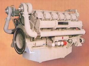 (This engine should not be confused with the earlier air-cooled Vega introduced in 1959/60 - see above.)
Launched in 1986, the design of this engine was a joint venture between Paxman and Dorman Diesels of Stafford, when the two companies were part of the GEC Diesels Group. Dorman needed an engine to replace their 6¼" (159mm) bore Q and S range engines which were aging and becoming less cost competitive. It was evident that considerable increases in power could be attained from the same size of engine by a re-design to accept higher cylinder pressures and by taking advantage of developments in turbocharging and fuel injection equipment. The attraction for Paxman was that highly rated vee engines of 160mm bore would replace those in the power range of the 7¾" bore Ventura (YJ) engines. Initial design and development was aimed largely at the generator set market, a market in which Dorman had traditionally been strong.
The intention was that Dorman would manufacture and sell the in-line versions of the engine and Paxman would produce the vee form engines. It was also originally intended that these engines would be manufactured in volume and be available from stock in a standard form to achieve competitive pricing and speedy delivery. Those aims were never fully realised.
The Vega was the first Paxman engine to be fitted with unit pump injectors where the fuel pump and injector are combined in a single unit. Each pump is driven from the main camshaft through a conventional rocker lever. The benefits of this arrangement include reduced costs, ease and speed of replacement, and the elimination of high pressure pipes between fuel pumps and injectors (with the inherent fire risks in the event of a pipe fracturing). The use of side by side connecting rods marked a move away from fork and blade connecting rods to reduce costs. The engine was aimed at industrial applications and markets in which cost was a critical factor.
The 12 cylinder versions can produce 1,075 kWb at 1,500 rpm (continuous rating) with a sprint rating of 1,182 kWb.
- Bore and Stroke: 160mm x 190mm. Swept volume 3.82 litres per cylinder.
- Cylinder configurations: V12 and V16 produced at Colchester. In-line versions produced by Dorman at Stafford.
- Power output: 970 kWb (1,300 bhp) to 1,576 kWb (2,113 bhp) at 1,550 rpm.
- Other features: Monobloc iron casting crankcase; 60° vee; compression ratio 13.8 : 1; Lucas Bryce unit pump injectors; pump injectors and valvegear operated by single camshaft located in the vee; cross flow cylinder heads; canister type disposable oil filters.
- VP185
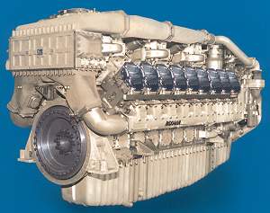 By the mid-1980s the Valenta was coming towards the end of its design life and facing stiffer competition in the market. GEC Diesels was contemplating the idea of a new basic engine design to be shared between Ruston and Paxman. The intentions were that it should have a standard bore size and many common components, with Ruston developing the medium speed version and Paxman the high speed one. J N (Nigel) Ramsden, Paxman's Technical Director, argued that this was not a practical proposition because of unique factors relating to high speed engine design. He successfully persuaded Dr H J (Harvey) Perkins, Managing Director of GEC Diesels, that Paxman needed to develop its own next generation engine. Within a few weeks of W L (Will) Pavry coming back to Paxman as its new Managing Director, Nigel Ramsden submitted a formal proposal for a new engine to Paxman's Management Committee in November 1987. The document explained the competitive market considerations and contained an outline design together with costings and time schedules for the design and development of different sizes of the engine. Will Pavry recalls that the proposal was accepted with very little debate and that Dr Harvey Perkins took a close and supportive interest in the project.
Much of the credit for the VP185 must go to Nigel Ramsden whose ideas, drive, energy, forceful personality and absolute commitment ensured that his plans for the new engine were realised. The detailed design was the work of a relatively young team of designers led by Ian Drake. However, Nigel and Ian would be the first to emphasize the important contributions made by Barry Whitfield, Chief Performance Engineer, Ron Miller, Chief Stress Engineer, and Dave Cardy's team in Development. (Work is in progress to record the story of the VP185 in much greater detail.)
The VP185 cost around £15 million to develop and design started in late 1987. This was the first Paxman engine to be designed using CAD (Computer Aided Design) and computing techniques for predicting performance and stress. The first (12 cylinder) development engine ran on 31st August 1991. It reached its full power performance target of 2,611 kWb (3,500 bhp) at 1,950 rpm on 4th February the following year. The 12 cylinder version was officially launched on 26th May 1993 in impressive style in the Company's Training School. The 18 cylinder version was introduced in 1998. The latter, weighing 10.2 tons, has a maximum output of 4,000 kWb at 1,950 rpm.
Among the main differences from the Valenta are its 90° vee to reduce the height of the engine (rather than the more usual 60° vee); unit pump injectors, eliminating the two additional camshafts required by the Valenta to drive fuel pumps; side by side connecting rods to reduce manufacturing costs; higher firing pressures; increased power output; improved fuel consumption and emissions performance. The number of gears in the main train was reduced from 10 to 2. The two-stage turbocharged, intercooled and aftercooled charge air system is innovative. The standard 12 cylinder version of the engine, the 12VP185, has 6 automotive type turbochargers fitted in a single turbocharger housing placed on top of the engine. On the 18 cylinder version there are three turbocharger housings, each with three turbochargers. A variant of the standard 12VP185 is the 'two box' version which, instead of the single turbocharger housing, has two turbocharger boxes of the same design as those on the 18VP185. The page VP185 Turbocharging Arrangements explains the three arrangements in detail and gives information about 'two box 12' orders and applications.
Despite a healthy order book for the VP185 (or perhaps because of it !), MAN transferred manufacture of this world-beating Paxman engine from Colchester to the Mirrlees factory at Stockport in 2003. The last production (i.e. new) VP185 engine to be built at Colchester, before the transfer, was despatched from the Works on Monday 15th September 2003 to a railway customer. At the time that was thought to be the end of the Company's proud 138 year history of manufacturing at Colchester. However, MAN had under-estimated the skills and experience needed to build this advanced high-speed engine and, indeed, to machine the required components. The problems which ensued, and the heavy financial losses which were incurred, led to a decision to stop offering the engine to the market. This did not dampen strong customer demand for the engine so VP185 engine building recommenced at Paxman's Colchester Works in the summer of 2005. Orders have included ten 'two box 12s'. In early August 2007 an order was signed for three 18VP185s for a fast patrol boat for the Vietnam Marine Police. These are to be built at Colchester, as were three of another six VP185s which have already been delivered to the same customer.
- Bore and Stroke: 185mm x 196mm. Swept volume 5.27 litres per cylinder.
- Cylinder configurations: V12 and V18
- Maximum Power Ratings - all at 1,950 rpm :
12VP185: 2,610 kWb (3,500 bhp).
12VP185 'two box': 2,670 kWb (3,580 bhp).
18VP185: 4,000 kWb (5,362 bhp). - Other features: 90° vee; unit pump injectors; side-by-side connecting rods; maximum firing pressure 3,000 psi/207 bar; innovative two-stage turbocharging, intercooled and aftercooled; dry weights: 12 cylinder 7.46 tonnes, 18 cylinder 10.16 tonnes. Fuller details can be found on the VP185 Technical Specification as at 2004 and VP185 Technical Specifications announced in 2012 pages.
Acknowledgements: I would like to express my warm appreciation to all who have helped with information for this page, not least those who have spotted errors and pointed me on the right path. Some have shared knowledge gained from their personal experience of designing or otherwise working on particular engines, while others have allowed me access to invaluable documentary sources. I am particular grateful to several people whose names deserve special mention.
The late Vic Borley, who was for many years a Service Engineer then Customer Training Instructor with Paxman. His wide knowledge of Paxman 'heritage' and modern engines, his extensive practical experience of working on most of them, his support and encouragement were all immensely valuable. The late Alex Walford was another ex-Paxman man to whom I regularly turned for help and guidance. Alex's long Paxman experience coupled with his encyclopaedic knowledge of engines, both diesel and steam, was recognised and respected worldwide. The late Denis Turner, a long serving Paxman man who was the authority on Paxman diesel rail traction and applications engineering generally, contributed a wealth of information and answered countless queries. I am also indebted to Don Meiklejohn, formerly Technical Support Engineer at Paxman, for his help with access to historical records relating to the Company's engine production from the late 1940s to the 1970s.
John Cove has provided substantial and most interesting contributions on post-war engines, gained during his time at Paxman. John joined Paxman in 1948 as a Forensic Investigator attached to the Experimental Department with subsequent appointments including Assistant Service Manager, Quality Engineer, Chief Diesel Engineer, Manager - Engine Division, and in 1966 Marketing Director. John was thus in a position to observe Paxman's engine activities from a number of different positions during one of the busiest and most exciting periods of the Company's diesel business.
On the design of more recent Paxman engines I am indebted to the late Roy Dingle, who was primarily responsible for the design of the Ventura and Valenta, to Bill Cox who worked on the design of the Vectara and the (1986) Vega, and to Ian Drake who, under Nigel Ramsden, headed up the team of designers responsible for the VP185. Additional input on the VP185 has been received from Will Pavry, formerly Managing Director.
There must be other individuals who should be mentioned but whose names escape me for the moment. I hope they will be as forgiving as they have been helpful and that all who have contributed will feel the result was worth the effort.
Richard Carr
Reference
1. Yachting World and Motor Boat Journal, Sept 13th 1935.
2. Paxman's World, No 5, March 1949, p.25.
3. Paxman Bulletin, January 1966.
4. Diesel Railway Traction, July 1951, pp.145-6, 156.
Further Reading:
Clover, M F and Edwards, A J: Some problems in the design and development of fork and blade connecting rods for vee-form engines, Symposium Mech Design of Diesel Engines, IMechE, London 1967.
Dingle W R and Stent J: Some problems in the design and development of a compact lightweight vee-form diesel engine, 7th International Congress on Combustion Engines, Paper A13, CIMAC, London 1975.
The Paxman 'Valenta' Diesel Engines - M F Clover, MA, CEng, MIMechE. GEC Journal of Science & Technology, Vol 44, No 2 1978.
Institution of Diesel & Gas Turbine Engineers Transactions - Design and Development of Paxman SE vee Engine, M F Clover MA CEng MIMechE and B Cropton. October 1988. Pub 446.
Institution of Diesel & Gas Turbine Engineers Transactions - The Design and Development of the 12VP185, J N Ramsden CEng MRAeS, Technical Director, GEC ALSTHOM Paxman Diesels Limited. Publication 497.
Page updated: 27 Jan 2025 at 17:23