
Torsional Vibration and Viscous Dampers
Preface: The Paxman Sales Engineers' Handbook says "The subject of torsional vibrations is extremely complex and the calculations quite involved". (1) That is perhaps an understatement! Such a highly technical subject may seem a rather abstruse topic for inclusion in a history of Paxman. Torsional vibration can be a particular problem in large, high-speed, multi-cylinder diesel engines: the type in which Paxman has specialised for more than 75 years. Consequently it became essential for the Company to acquire an in-depth understanding of the subject and of the steps which can be taken to minimise the risks arising from torsional vibration. The key figures in this story are the handful of Paxman engineers who became acknowledged authorities on torsional vibration problems and practical solutions for overcoming them. Their knowledge, understanding and abilities in this field earned them reputations and respect far beyond the confines of the Company. The story of Paxman's success in dealing with the challenges of torsional vibration provides a good illustration of the high levels of specialist knowledge and skills which have characterised the Company's engineers throughout the history of the business.
What is torsional vibration and why is it a problem?
Torsional vibration occurs in crankshafts of reciprocating internal-combustion engines and the coupled drive line systems of such engines. The firing pulses of an engine's cylinders create a pulsating torque, rather than a steady unidirectional torque, in the crankshaft. The pulses act in one direction as each cylinder fires, and then in the opposite direction during each cylinder's compression stroke. The variations in cylinder pressure throughout each complete engine cycle produce forces of changing magnitude and direction at the engine crankshaft. The end of the shaft attached to the flywheel rotates at a near-constant speed as the flywheel, through the inertial forces acting upon it, fulfils its function. At the free end of the crankshaft angular oscillations which are superimposed on the shaft rotational speed, resulting from the firing impulses of the cylinders, produce larger torsional vibration displacements than those at the flywheel end of the shaft. These angular displacements and resulting vibratory torques produce vibratory stresses in the material of the crankshaft. Normally these stresses are within the design limits for the shaft. However, if the frequency of these excitation torques is allowed to coincide with the torsional natural frequency of the crankshaft a resonant condition can arise and lead to damagingly high levels of vibratory stresses and subsequent fatigue failure of the shaft material. Such failures are always in fatigue mode and normally start from 'stress raisers'. In crankshafts the stress raisers which are significant for torsional fatigue are the crankpin and journal blend radii and the oil holes drilled into the main bearings towards the crankpins. Once a small crack has started, the stress raiser effect becomes much greater and further propagation is inevitable.
Fatigue cracks initially propagate relatively slowly at a rate depending on load until there is insufficient remaining metal area to transmit the power and rapid failure then occurs. After a torsional fatigue failure the fractured surfaces tend to follow a spiral shape and the area of initial slow propagation always appears relatively smooth, while the final rapid failure area is rough as the last remaining metal is simply torn apart.
Engine-generated excitation frequencies are related to harmonics of the engine speed. When one of these frequencies synchronises with a shaft system natural frequency, the engine is said to be running at a 'critical speed'. Such speeds usually make their presence known by a rumbling noise caused by moving parts, such as crank journals, pins, gudgeons and pistons hammering from side to side in their respective clearances, and by backlash in gear teeth.
One hardly need add that crankshaft failure is exceptionally costly although secondary damage to other engine parts is not usually excessive. After the crankcase or engine housing, the crankshaft is generally the most expensive single engine component. The strip-down and reassembly needed to fit a replacement is also expensive and time-consuming. Furthermore, the high cost of large crankshafts is such that a spare may not be available as a stock item but have to be manufactured to order, possibly with a lead time of months rather than days. All the time the engine is out of service, the costs mount up for the owner.
For engines which are designed for one particular application, such as driving an alternator, in which they will run at a constant set speed, it is possible to modify the system inertia and hence the natural frequency by adding additional rotating mass to the engine's free end, in order to move critical speeds away from a fixed running speed. A similar modification to natural frequencies can be imposed by introducing a flexible coupling drive between the engine and the machine it is driving.
Paxman has, since the 1930s, specialised in the design and build of high-speed diesels intended for use in a variety of applications. In several of these, such as marine propulsion, oil-well drilling and some types of rail traction, there has been a requirement for engines to operate not at one fixed speed but over a wide speed range. Consequently torsional vibration became an important matter which it was essential for the Company to address in depth.
Factors governing the risk of torsional vibration problems
The risk of encountering torsional vibration problems is influenced by six main factors: (a) the torsional natural frequencies of the crankshaft, (b) the engine's firing pressure, (c) its rotational speed, (d) its number of cylinders, (e) the firing order and the bank angle of vee engines and (f) inherent damping in the system.
- A crankshaft's length, geometry and balance weight arrangement fundamentally influence its torsional stiffness and inertia and hence its natural frequencies.
- Compared with spark-ignition engines, diesels have high compression-ratios. Most diesels are also turbocharged. The combination of high compression-ratios and high charge-air boost pressures results in high firing pressures. The latter impose very heavy loads on pistons, connecting rods and crankpins, with correspondingly greater pulse effects. These increase the risk of troublesome torsional vibration occurring in the crankshafts of diesel engines compared with those of petrol engines with their much lower compression-ratios and firing pressures.
- The risk of encountering torsional vibration problems can increase markedly as engine speeds increase. As an engine's speed increases so does the frequency of its firing impulses. As the frequency of the latter increases, so does the risk of these vibrations exciting the crankshaft's natural frequencies for torsionally stiff shafts having high natural frequencies.
- The risk of torsional vibration problems increases with the number of cylinders in a given type of engine. There are two factors at play here. First, as the number of cylinders increases so does the number of firing pulses per crankshaft revolution, increasing the potential for exciting torsional vibrations. The second factor is the length of the crankshaft. In, say, a four cylinder engine the crankshaft is relatively short and rigid. The amplitude of the crankshaft's deflection on each cylinder's firing and compression stroke is comparatively small and torsional oscillation is minimal. As the number of cylinders increases, the crankshaft has to be lengthened accordingly. The longer a crankshaft is, the less rigid it becomes along its length. It is thus more likely to flex and experience greater amplitudes of torsional oscillation. The higher as well as the lower natural frequencies of longer shafts are more likely to be excited by operational frequencies.
- The firing order can have a major impact on the risk of torsional vibration. The choice of the best firing order for ideal torsional vibration characteristics is not usually the best for ideal exhaust and turbocharging arrangements. A compromise between these two requirements is usually necessary.
- The inherent damping in the system plus the damping factor introduced by fitting a viscous damper will significantly limit the amplitudes of vibration which occur at or near any resonant frequencies associated with engine critical speeds.
As previously mentioned, since the 1930s Paxman has chosen to specialise in the design and manufacture of large, high-speed diesel engines with, typically, 12, 16 or 18 cylinders. It is very much this type of engine which is likely to encounter torsional vibration problems, particularly because of the factors (b), (c) and (d) described above. As the Company increased the speeds and power outputs of its engines it became essential to acquire an in-depth understanding of this highly technical subject and to find practical solutions to the potential problems.
Torsional Vibration Calculations
A major part of the torsional vibration engineer's work is doing calculations to determine the natural frequencies of a crankshaft and the complete driven shaft systems and where to expect 'critical speeds' within an engine's normal operating speed range. The calculations need to be made not solely for the engine itself but for the engine and any machinery coupled to it. Information required for the complex calculations includes the stiffness, dimensions and material properties of all shafts, the inertia of rotating masses within the engine such as the flywheel, crankshaft and damper, the inertia of rotating masses in any driven machinery such as gear shafts, alternator armature or marine propeller, the configuration (crank angles, etc.) of the crankshaft, the engine's firing order, its number of cylinders, operating speeds and speed range. The validity of calculated natural frequencies and vibration amplitudes needs to be verified from an operating engine. The results of calculations are therefore checked by running the engine on a test bed and using a Torsiograph to record the frequency and amplitude of vibrations in the crankshaft. From this record and the calculations an accurate knowledge of the behaviour of the shaft can be acquired.
From the 1940s it became standard practice within Paxman for the Company's torsional vibration engineers to do the calculations for resonant frequencies and obtain Torsiograph recordings for each type of engine and its driven machinery. Having identified any critical speeds within the engine's normal range of operating speeds, it was then the responsibility of these engineers to advise on appropriate measures to avoid torsional vibration problems when the engine was in service. Before the arrival of the viscous damper, which is described later on this page, steps which could be taken to avoid problems included altering the resonant frequency of the crankshaft by altering the mass of one or more rotating parts by, for example, adding mass to the free end of the crankshaft or by adding a flexible coupling of calculated stiffness between the engine and its driven machinery or by a combination of these.
Before the viscous damper became available, it was considered that for a constant speed application, such as driving a generator, only the normal operating or working speed needed to be free of critical frequencies as, generally, any criticals at lower speeds would be quickly passed through as the engine was run up to speed. However, in many applications of Paxman engines, such as marine propulsion, engines were (and still are) required to operate over a wide speed range. Until the arrival of the viscous damper in the 1950s, variable speed applications sometimes had to have 'barred' speeds at which the engine could not be run for any length of time without the risk of damage. Not only was the safety of the crankshaft then entirely dependent on the operator but for some applications, such as oilwell drilling, barred speeds were simply not acceptable to the customer.
David Legerton joined Paxman's Torsional Vibration Section in about 1967. He recalls that in those days the Company's torsional vibration calculations were done in ledger type books in which it was possible to look up all previous calculations. During the late 1960s or early 1970s arrangements were made for some of the calculations to be done on the University of Essex's computer which used a punched card system for data input. In the 1980s the late Leo Crawley, Paxman's Principal Vibration Engineer from 1958 to 1990, adapted a small BBC microcomputer to do torsional vibration calculations. This was in the very early days of personal microcomputers. Leo was a keen electronics enthusiast in his spare time and not only did he write the calculation programs (in machine code, the lowest level programming language and the most demanding to work with), he also substantially modified the hardware of his microcomputer to suit his particular requirements. (2)
The Viscous Damper Solution
The device adopted by Paxman in the 1950s to overcome torsional vibration problems was the viscous damper. Since that time the Company has used this type of damper on all its engines with the single exception of the 18 cylinder version of its latest engine, the VP185. The purpose of the damper is to 'damp' or reduce the torsional vibrations in the crankshaft and to keep the material stresses within permissible limits to eliminate or minimise the risk of failure. Before moving on to the history of Paxman's involvement with the viscous damper, a brief description of the device may be helpful.
The viscous damper is a circular shaped unit which is bolted to the free end of the crankshaft. It consists of an annular sealed casing within which there is a massive ring of steel free to rotate on a central bearing. There is a small and closely controlled gap between the ring and the casing which is filled with a high viscosity silicone fluid, dimethyl polysiloxane.
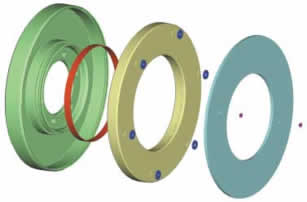
On the left in the above diagram is the main section of a viscous damper's casing, the part
which is bolted to the free end of the crankshaft, and on the far right is its cover.
In the centre is the inertia ring which is free to rotate inside the casing.
(Diagram by kind permission of Metaldyne International UK Ltd.)
During normal operation both the casing and inertia ring revolve together as one mass due to the high viscosity of the silicone fluid. If the crankshaft seeks to vibrate in the torsional mode, the outer casing has to vibrate with it. The internal ring is not fixed to the casing and because of its inertia tries to continue rotating steadily. The resistance produced by shearing of the viscous silicone fluid causes the ring to exert a restraining force on the casing thus damping the torsional vibrations. This enables an engine to run at what would otherwise be critical speeds for torsional vibrations, by preventing these vibrations from building up to a level which would cause damaging stresses in the crankshaft.
The shearing of the silicone fluid generates heat which has to be dissipated through the external surfaces of the damper. This can be either to air in the case of an externally mounted damper or to the engine's lubricating oil when the damper is mounted inside the engine casing. Failure to ensure a satisfactory rate of heat dissipation leads to overheating and early failure of the damper as the silicone fluid breaks down at very high temperatures.
The Arrival of the Viscous Damper at Paxman
In the early 1950s Geoffrey Bone (who joined Paxman in 1945 and was its Managing Director from 1954 to 1964) came back from a trip to the USA with a small viscous damper in his baggage and a firm conviction that this was the way to go for the future avoidance of torsional vibration problems. The damper was made by the Houdaille-Hershey Corporation (name shortened to Houdaille Industries in 1955).
It is not known what commercial arrangements were made with Houdaille to use their technology. However Ray Roxby and Alex Walford recall that in the early 1950s Paxman developed larger dampers of this type for its engines and initially manufactured them in-house. Neil Avis believes the Company originally made them for use on the YL engine. Manufacture of dampers did not continue for long at Colchester. Geoffrey Bone made arrangements for Holset Engineering to design and manufacture them. Not a surprising move as Holset's flexible coupling and viscous damper business was headed by an ex-Paxman man, Paul Croset, who possessed a detailed knowledge of Paxman engines and torsional vibration issues.
The use of viscous dampers did not remove the necessity to check for critical speeds and fit suitable flexible couplings to certain sets. They did, however, reduce the vibration amplitudes at the critical speeds so that it rarely became necessary to make individually tailored masses for attaching to crankshafts to overcome potential torsional vibration problems.
An early problem with viscous dampers
Paxman's initial application of viscous dampers was not without problems. The Company supplied a number of engines to Shell to power oilwell drilling barges for use on Lake Maracaibo in Venezuela. For this duty the engines had to run for very long periods at any speed within their range. All went well for a year or so and then a spate of failures began. The initial failures started in the slotted driving plate connecting the engine to the hydraulic coupling but crankshaft failures followed soon after (for more of the technical background, see additional note at foot of page). Paxman had an engineer, Freddie Webb, based in Venezuela, but he could find no reason for these serious failures. Furthermore, spare crankshafts were being used at a great rate and the lead time for new crankshafts was over one year. The Company could not afford to allow Shell to have to cease production because of lack of spare crankshafts.
John Cove was sent out to Venezuela in 1956 to investigate the problem. On that trip he was accompanied by Leo Crawley, then Paxman's torsional vibration expert, as torsional vibrations were suspected despite the fact that all these engines were fitted with dampers. Alf Herbert, who was in charge of Paxman's spare parts service, was also with John, Freddie and Leo, but on a separate remit to ensure adequate spares service from a newly appointed agent in Maracaibo.

(left to right) Alf Herbert, Leo Crawley and Freddie Webb travelling on the high-speed launch on
Lake Maracaibo in 1956, which took them and John Cove from Maracaibo towards Lagunillas,
to the drilling barges operated with Paxman engines. (Photo courtesy of John Cove.)
As soon as John Cove saw the damaged engines he knew the dampers had failed. Paint on the dampers had become so hot that it had blistered, and examination of the broken crankshafts showed that the type of failure was typical of that caused by torsional fatigue. Torsional vibration tests carried out by Leo Crawley on engines which had not yet failed revealed that the dampers on some of them were not working. From this John knew that more crankshaft failures could be expected once the initial fatigue cracks had had time to propagate further.
John got a local machine shop to cut open the defective dampers and found that in some the silicone fluid had lost all its viscosity and ran like water, while in others the fluid, through heating, had turned into a black solid like synthetic rubber. He returned to the UK with samples and Holset investigated.
The inertia ring and its bearing were plated with cadmium to reduce the tendency for scuffing of the bearing surfaces. Holset's investigation concluded that the silicone fluid had become contaminated by chemicals used in the cadmium plating of the ring and its bearing. The mass ring had a bronze bearing which was pressed into it and this bearing in turn ran on a steel surface inside the casing. The bearing was fitted into the ring before the whole assembly was put into the plating bath. During plating, fluid had managed to enter the small gaps and clearances between the bronze bearing and the steel ring. The washing process after plating failed to remove all of it from these small recesses so plating fluid gradually seeped out during operational service and contaminated the silicone.
Holset changed either the design or manufacturing process, or both, and that appears to have been the end of that particular problem.
Paxman's Torsional Vibration Engineers
Two key personalities in the early history of Paxman's interest in torsional vibration were Paul Croset and his father, Louis, both of whom worked for the Company in the 1940s. Paul Croset, who had served his apprenticeship with the Crossley Premier Gas & Oil Engine Company of Sandiacre, came to Paxman to advise on torsional analysis. He was Paxman's expert on torsional vibration matters until leaving to join the W C Holmes company at Huddersfield in December 1948, to start up and manage their new flexible couplings venture. This business became Holset, of which Paul became Managing Director and subsequently Chairman. (3) Paul Croset was awarded an OBE in 1967 (presumably for services to industry).
Louis Croset had joined Paxman as an engine designer during World War 2, having previously been Chief Designer at Crossley Premier. (4) The March 1949 issue of Paxman's World contained an article about the Company's Diesel Engineering Department within which there was a Design Department. Describing the latter it said: 'Head of this department is Mr L P Croset, who has some eight designers working with him. Mr Croset is a well-known figure in the engineering world for his design of small and medium-sized diesel engines'. (5) Ray Roxby recalls that Louis was absent from work due to serious illness during much of 1948. We know from another source that Joe Hind, who had previously worked for Paxman from 1940 to 1947, was brought back from Dennis Commercial Vehicles at Guildford and appointed Chief Designer, in Louis's place, in January 1949. (6) Prior to this event, Louis had designed and patented a flexible coupling. It was this coupling which the W C Holmes company became interested in manufacturing and which led to it setting up the flexible coupling venture headed by Louis's son, Paul. In the June 1950 issue of Diesel Railway Traction it was announced that 'Louis P Croset, until recently Chief Diesel Engine Designer with Davey Paxman & Co, has joined W C Holmes in the capacity of Consulting Engineer in the Holset coupling and damper department'. (7) Ray Roxby recalls that Louis Croset, while at Paxman, started work on designing the vee form version of the RPL engine.
When Paul Croset left Paxman in 1948 to join W C Holmes, Doug Braund was appointed Torsional Vibration Engineer in his place. Doug joined Paxman as an apprentice in 1938 (8) and, after completing his training, worked as a Test Engineer in Paxman's post-war Experimental Department before moving into the Torsional Vibration section. He came to be another widely respected authority on torsional vibration. A few years later, after making a valuable contribution at Colchester, Doug joined Paul Croset at Holset (probably c.1958) and in time was appointed a Director of that company. He was a contributor to A Handbook on Torsional Vibration (9), one of the leading texts on the subject.
 Doug Braund's successor at Paxman was Leo Crawley. Leo first worked for Power Jets at Lutterworth as an apprentice under Frank Whittle, inventor of the jet engine. At Lutterworth he progressed to become Scientific Assistant in the Vibration Department. Leo joined Paxman's Experimental Department in November 1948 (10), having been recruited by Geoffrey Bone, the then head of that Department, who had himself worked with Frank Whittle at Power Jets before coming to Colchester. In 1958 Leo was appointed head of Paxman's Torsional Vibration section and became one of Britain's leading experts in vibration calculation and measurement. In 1988 he was appointment chairman of British Marine Technology's steering committee for drawing up a standard for noise and vibration on board ships. (11)
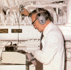
Photo: Leo Crawley taking vibration readings from a Ventura engine on test.
It was a great shock and sadness to all of us at Paxman when in April 1990 Leo died in hospital after a short illness. He was aged only 62 and had over 41 years service with the Company. My personal memory of Leo is of a modest unassuming man, always friendly, cheerful and very helpful: a real gentleman. The same opinion has been echoed by others who worked closely with him and knew him better. Leo was exceptionally able in what is universally recognised to be a highly technical discipline. Kevin Hosking, a former colleague of Leo, has described him as 'incredibly clever' and having 'an outstanding knowledge of noise and vibration'. No one at Paxman would argue with that assessment. He was much liked and well-respected both for his technical knowledge and his attractive personal qualities.
Among those who assisted Leo on torsional vibration were Doug Appleby, who during the latter part of his career was Paxman's Overhauls Manager, and Brian Cosson who was involved with the initial moves to use computers for torsional vibration calculations. Brian left the Company to join Lloyds Registry of Shipping Technical Department where he progressed to the position of Torsional Vibration Surveyor. Another protégé of Leo was David Legerton who joined Paxman in 1962 and served a five-year Student Apprenticeship. After a time in Applications Engineering, David moved to the Torsional Vibration section in about 1967 where he became Leo's right hand man. David left Paxman in 1975 to join the CEGB's Scientific Services Department as a Research Officer, working on vibrations associated with power station machinery and plant. After David left, Leo was ably assisted for some years by Erik James who had been on the same Higher National Diploma course as David during his training.
After Leo Crawley's sudden unexpected death I was asked to recruit David Legerton back to Paxman to fill Leo's position. No difficult selection decision was called for on this particular assignment. David's knowledge and experience of torsional vibration and Paxman engines made him the ideal candidate for the job. He was also well-liked and respected. Fortunately the offer of the position of Principal Vibration Engineer was accepted and David rejoined the Company in July 1990. It had been envisaged earlier that David would return to Colchester to spend some time with Leo, before Leo retired, so that there could be a smooth handover of responsibilities. In the circumstances David was plunged straight in at the deep end without the benefit of a handover period. David's unassuming manner, courtesy, cheerful friendliness and helpfulness have often struck me as being remarkably similar to Leo's character traits. Did he inherit these, as well as his technical expertise, from his former mentor? David left in December 2002 when the Engineering function at Colchester was reduced to a small handful of people to support existing engines. He was the last in Paxman's succession of remarkably talented torsional vibration engineers whose contribution was so important to the Company's success in the field of high-speed diesels.
The Holset Viscous Damper Business
Reference has already been made to the origins of the Holset business, when W C Holmes established its flexible coupling department to make and market couplings designed by Louis Croset. As previously mentioned, Paul Croset joined Holmes in early December 1948 after being persuaded to move to Huddersfield to head up the new venture. Paul was later joined by his father as Consulting Engineer and by Doug Braund who rose to be a Director of Holset. It is noteworthy that three ex-Paxman engineers, each well-versed in torsional vibration, played major parts in the establishment and growth of what was to become the leading British manufacturer of flexible couplings and viscous dampers.
In late 1949 the question arose of what to call the new business. The name settled on was Holset, derived from the first part of HOLmes and the last part of CroSET. The venture now began to trade as the Holset Division of W C Holmes. At the end of March 1952 the Division was formed into a limited company, the Holset Engineering Co Ltd, and Paul Croset was appointed its first Managing Director.
With his former background as a torsional vibration engineer, it is not surprising that Paul Croset set about convincing Holmes's Directors that the new venture should include vibration dampers: a good fit with the flexible couplings product and markets. In 1954 Holset obtained a licence from Houdaille to manufacture viscous dampers in the UK. This fits in with Alex Walford's recollection that in 1952, shortly after he started work at Paxman, Paxman was developing and building its own viscous dampers but that this did not continue for long. Other ex-Paxman engineers also remember that Paxman did not make dampers for long but approached Holset to make and supply them. Since the mid-1950s all Paxman engines have been fitted with Holset viscous dampers with the exception of the 18 cylinder version of the VP185 which has a tuned damper. Holset also became a major manufacturer of Büchi turbochargers, some of which were supplied to Paxman.
In 1973 the Holset business was acquired by the Cummins Engine Company Inc which subsequently appointed Paul Croset as Holset's Chairman. Also in 1973 the company moved from Huddersfield to its present location in Halifax, Yorkshire. In June 1997 Holset's Vibration Attenuation business was acquired by Simpson Industries of Plymouth, Michigan, USA. Metaldyne was formed in 2001 and in January 2007 the business was acquired by the Asahi Tec Corporation of Japan. Since that date there has been a further change of ownership but as at 2011 the Simpson/Holset viscous dampers business still trades as Metaldyne International UK Ltd.
Current Practice
Today, large diesels of the Paxman type are generally fitted with either a viscous or a tuned type of damper. As previously mentioned, Paxman has continued to use 'Holset' viscous dampers on all its engines except the 18 cylinder VP185 which has a tuned damper for reasons explained below. On earlier Paxman engines, such as the RPH Series, the damper was fitted externally and cooled by the surrounding air. The Ventura, Valenta and 12VP185 all have viscous dampers mounted internally, where the lubricating oil splashing around in the crankcase is sufficient to cool them. Most of the engines built by MTU (Motoren und Turbinen Union), one of Paxman's main competitors in the high-speed diesel market, use the tuned type.
The 18VP185's Tuned Damper
When Paxman was considering the design of the 18 cylinder version of the VP185, there was a desire to avoid having to fit two dampers as on the 16 and 18 cylinder versions of the VP185's immediate predecessor, the Valenta. The prototype 18VP185 development engine was therefore fitted with a Holset tuned damper. Paxman found that this, one of the earliest tuned type made by Holset, did not perform as well as had been hoped. The other difficulty was the very large size of the Holset version at that time. Consequently it was decided to use instead a tuned damper from Geislinger GmbH of Austria. This consists of a hub and inertia ring, with the inertia ring being driven through a set of radially aligned leaf springs which are flooded in oil. The Geislinger tuned damper is more compact than a viscous damper of the same damping capacity but is more expensive. An important advantage is that its operation can be adjusted to suit the characteristics of the particular type of engine to which it is fitted; this fine-tuning is done in cooperation with the manufacturer. A drawback of the tuned damper is that its operation requires it to be connected to the engine's lubricating oil system. The damper, therefore, needs an oil feed and, more problematically, an oil drain. Oil is drained from the damper through jets located in the periphery and so, for practical reasons, the tuned damper must be mounted inside the engine casing. (As mentioned earlier, a viscous damper can be mounted either internally or externally.)
References
1. Paxman Sales Engineers' Handbook, Davey, Paxman & Co, c.1967/68. Published for restricted circulation within the company. p.287.
2. As related to the author by David Legerton during a discussion in February 2008.
3. HTi Magazine, Edition 6, 2006, p.2, published by Cummins Turbo Technologies.
4. HTi Magazine, Edition 1, p.4, published by Holset Turbochargers.
5. Paxman's World, No 5, March 1949, p.4.
6. Diesel Engineering, Winter 1980, 'Some memories of 45 years in the diesel industry', C J Hind CEng FIMarE, pp.180ff.
7. Diesel Railway Traction, June 1950, p.138.
8. Paxman Board Minutes of the meeting held on 8th December 1938 record that Douglas Braund's apprenticeship indentures were sealed at this meeting.
9. A Handbook on Torsional Vibration, compiled by E J Nestorides, Cambridge University Press 1958.
10. Paxman's World, No 4, December 1948, p.26.
11. Essex County Standard, 27th April 1990, p.54 (Leo Crawley obituary).
Further Reading
Paxman Sales Engineers' Handbook, pp.287-290.
Hillier's Fundamentals of Motor Vehicle Technology - Book 1, 5th Edition, V A W Hillier & Peter Coombes, Nelson Thornes 2004, pp. 49-50.
Acknowledgements: Not being an engineer, I have been heavily dependant on Paxman ex-colleagues and other professional engineer friends for their help and guidance while compiling this page on a highly technical subject. I am deeply indebted to the following for their assistance and recollections: John Cove who joined Paxman in 1948 as a Forensic Investigator attached to the Experimental Department and whose subsequent appointments in the Company including Assistant Service Manager, Quality Engineer, Chief Diesel Engineer, Manager - Engine Division, and Marketing Director; David Legerton, formerly Principal Vibration Engineer, MAN Diesel Ltd, Paxman; Ian Drake, Chief Design Engineer and John Benham, Senior Product Engineer of MAN Diesel & Turbo UK Ltd; Ray Roxby, formerly Chief Design Engineer, GEC Alsthom Paxman Diesels; Alex Walford, formerly Principal Engineer - Mechanical, ALSTOM Engines Ltd, Regulateurs Europa; Kevin Hosking, formerly Engineering Manager, GEC Alsthom Paxman Diesels; Shaun Login, Senior Product Engineer, Metaldyne International UK Ltd.
Additional Note on failures in Venezuela
John Cove has provided the following background: -
"I was pretty certain before I went to Venezuela that the failures were due to torsional vibrations although not everyone in Colchester initially shared this view.
The crankshaft failures were preceded by a spate of failures of the driving plate which connected the engine to the Voith Schneider scoop-controlled hydraulic coupling. This driving plate was bolted to the crankshaft flange and had a diameter of about 2' 6" or maybe 3' which was the diameter of the fluid coupling drum and it was bolted to the drum by a ring of bolts right at its periphery. The plate was about 3/8" thick and to make it a bit flexible in case of alignment problems it had a number of rings of sausage shaped slots cut in it. The first sign of trouble was that these plates started cracking at the ends of the slots. The design office concluded that the slots had weakened the plates too much and so they had some plates made without any slots and air freighted them out. Our engineer Freddie Webb fitted them in place of the cracked ones and immediately reported back that they caused serious increase in vibration.
The research department had a fitter called Maurice Herbert, who was based in the 'hush-hush' building near the works pond and was occupied in making up special gear as required for our experiments. In order to enable the torsional vibration doubters to be convinced we got him to make a scale model of the drive plate out of thin cardboard complete with slots. He fixed the outside edge into a solid piece of plywood and mounted a smaller piece to represent the crankshaft flange. When you applied torque to the inner piece you could see the plate flexing about the very places where the drive plates had been cracking. I was sure therefore that there were torsional vibrations although we did not know what had caused them so Leo and I were sent out to check this as in the meantime crankshafts had started breaking.
I saw an engine running with a damper blackened by heat and predicted that the crankshaft would ultimately fracture. It took a year to do so and this indicates how low the average load is on a drilling engine when it is just operating the drill rather than the slush pump."
© Richard Carr 2011
Page updated: 16 FEB 2015