
Paxman RPL Diesel Engines
Technical Specification
This page reproduces the technical specification of the RPL series of engines, as published in Paxman Publication No 1208, Paxman Diesel Engines Series RPL, Vertical In-line and V-Type : 243 – 1420 bhp, which has a print date of October 1949.
More general information about the RPL range of engines can be found on the page Paxman Diesel Engines since 1934.
Specification
Paxman Series RPL diesel engines operate on the 4-stroke cycle, and have a bore of 9½in. (241.3 m/m) and a stroke of 12in. (304.8 m/m). Outputs are detailed (lower down this page), and the range comprises the following models:—
Vertical in-line engines
The 4-, 5-, 6-, and 8-cylinder vertical engines are normally of cast iron construction, but where considerations of weight or resistance to shock justify the extra cost, the '6RPL' and '8RPL' may be specially built with welded steel frames.
The 6- and 8-cylinder models are also available in pressure-charged form to develop up to 34 per cent increase in power.
V-type engines
The 12- and 16-cylinder V-type engines are built only with steel frames, and have an included angle between the two cylinder banks of 45 degrees. Either model may be pressure-charged.
 Cast iron construction
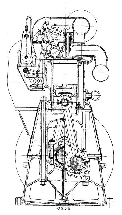
The bedplate, which carries the main bearings and forms the lubricating-oil sump, supports a number of 'A' frames, one in way of each main bearing. The cylinder block, mounted on these 'A' frames, is secured by means of high-tensile bolts which are carried right through from the bed and absorb all firing stresses. The construction is indicated in the cross-sectional drawing.
Right: Cross section of Vertical in-line RPL engine, cast iron construction.
As a result of the cast iron framing being retained in a state of compression, the greatest rigidity is obtained, while exceptionally large crankcase doors are permissible without impairing the strength. By this means ready accessibility is provided to all bearings, and the pistons complete with connecting rods may be removed through the crankcase doors without disturbing the cylinder heads or other parts of the engine.
Steel Construction
Built to Stevens' Patents, the fabricated steel frames for vertical in-line Series RPL engines are in one piece, and so designed that all firing stresses are absorbed mechanically by interlocking plates, as a result of which the welding is not subjected to load. The construction comprises a series of vertical 'sling' plates, one in way of each main bearing, cut away to pass over the cylinder head bolt plate at the top and under the main bearing housings at the bottom. The crankshaft complete with main bearings and housings is passed endwise into the frame.
In the case of 'V' models the construction is generally similar but the bedplate and crankcase are fabricated separately, and jointed at crankshaft level.
Bearers
In the case of engines of cast iron construction, alternative beds are available for stationary and marine applications.
Steel-framed engines are designed for mounting on a fabricated underbed which also forms the lubricating-oil sump. The arrangement of these underbeds may be varied to suit the requirements of the installation.
Crankshaft
The crankshaft is a solid steel forging machined all over and drilled for the pressure lubrication of the connecting rod large-end bearings.
Main bearings
These comprise renewable steel shells lined with anti-friction metal.
Cylinder liners
Series RPL engines are fitted with renewable wet-type liners of cast iron. Provision is made for expansion at the lower end. (see note in appendix at foot of page)
Pistons and gudgeon pins
Of aluminium 'Y' alloy, or special cast iron, the pistons are each fitted with four pressure and two oil control rings, the gudgeon pins being of the fully-floating type retained by circlips.
Connecting rods and bearings
Machined from steel stampings, the connecting rods are matched for weight and balance, the pressure-lubricated small-end bearing comprising a phosphor-bronze bush carried in the solid eye of the rod.
Vertical engines are fitted with large-end bearings comprising steel shells lined with anti-friction metal.
'V' engines are fitted with two types of rod, those for one bank of cylinders being forked and carrying separate steel large-end bearings lined internally with anti-friction metal. These bearings operate on the crank-pins and are turned externally to receive the 'blade' rods for the corresponding cylinders in the opposite bank. The latter rods carry steel shells lined with anti-friction metal.
Cylinder heads, and valves
The unit cylinder heads are of special-quality cast iron, and carry the vertical inlet and exhaust valves which are stellited to reduce pitting. The valve seats comprise renewable inserts, also stellited, so that a minimum of regrinding is necessary.
The valve rocker gear, which is totally enclosed and fully pressure-lubricated, is carried on an independent casting which also forms the upper half of the spherical antechamber and houses the fuel injector. The lower half and throat of the antechamber is of special heat-resisting steel.
Combustion system
Series RPL engines incorporate the patented Ricardo Mark III system of combustion, permitting the use of low injection pressures and single-hole fuel injectors. The principal advantages obtained are improved flexibility of running over a wide speed range, reduced maintenance costs, ability to operate on a variety of fuel oils, and the capacity to maintain tune and low fuel-consumption for exceptionally long periods of service.
Fuel pumps
Grouped together in a self-contained unit with integral camshaft, the fuel pumps (one per cylinder) are gear-driven from the main crankshaft. The pumps on 'V' engines are in two groups, one for each bank of cylinders.
Fuel injectors
Of the single-hole pintle-type, the fuel injectors are self-cleaning and practically unchokable in service. They are readily accessible and may be removed without breaking any cooling-water joints.
Camshaft
The camshaft is carried in pressure-lubricated bearings and is fitted with hardened and ground cams. Roller-type cam-followers transmit the motion through short push-rods to the valve rocker gear.
Camshaft drive
The camshaft is operated by means of a heavy roller-chain located at the driving end of the engine. Full provision is made for adjustment in the form of a jockey sprocket running on ball bearings.
Governor
Vertical in-line models are equipped with a totally-enclosed continuously-lubricated centrifugal governor mounted on the end of the camshaft, the engine speed being adjustable while running.
In the case of 'V' engines, a centrifugal hydraulic servo governor is driven by bevel gearing from the camshaft, the main lubricating-oil pressure being used as a medium to operate the fuel-pump control. By this means a small and compact governor of great sensitivity has been evolved, giving full control throughout the speed range of the engine. A feature is the exceptionally light adjustment designed to facilitate remote control. This governor is so arranged that, in the event of a failure of lubricating-oil pressure, the engine is shut down automatically.
For applications requiring its use, vertical engines can also be fitted with the servo governor at an extra charge.
Lubrication
Pressure lubrication is provided throughout, hand oiling being eliminated entirely. The oil pump is of the valveless gear type, entirely automatic in action, and a hand pump is provided for priming the system before starting. Vertical in-line engines are fitted with an independent lubricating system for the camshaft and valve gear, the pump for which is of the plunger type.
Standard engines are of the usual wet-sump type, but, when specially required, dry-sump lubrication may be provided at an extra charge. Filters and oil coolers are included in the equipment.
Pressure charging
The 6-cylinder and 8-cylinder vertical in-line models are available in pressure-charged form, using single-stage centrifugal blowers driven by exhaust gas turbines.
The 12-cylinder and 16-cylinder V-type engines may be pressure-charged either by Roots-type blowers, gear driven from the crankshaft, or by single-stage centrifugal blowers driven by exhaust gas turbines.
The V-type engines are fitted with two blowers in each case, one for each bank of cylinders.
Pressure-charging provides an increase in power of approximately 34 per cent.
Flywheel and coupling
Depending on the speed and duty involved, the engine may be either rigidly or resiliently coupled to the driven unit. When rigidly coupled, a balanced flywheel is bolted to the flanged crankshaft to form a solid half-coupling. Where a resilient drive is necessary, a flexible coupling is fitted in place of the flywheel.
In the case of the multi-cylinder 'V' models no flywheel is required, and a comparatively light barring disc is substituted, with consequent saving in weight.
Starting
Series RPL engines are arranged for starting by compressed air, which is applied directly to the cylinders by means of a distributor.
Cooling
Vertical engines are fitted with a positively-driven circulating water pump and inlet and outlet water manifolds. A separate pump and manifolds are provided for each bank on 'V' models.
Exhaust
Standard exhaust manifolds on vertical engines are of the uncooled type. Water-jacketed manifolds may be fitted if required at an extra charge.
'V' models are each equipped with two water-cooled manifolds, one for each cylinder bank.
Ratings
| Table of Ratings | ||||||
|---|---|---|---|---|---|---|
| MARK | BRAKE HORSE POWER | |||||
| 500 r.p.m. | 550 r.p.m. | 600 r.p.m. | 650 r.p.m. | 700 r.p.m. | 750 r.p.m. | |
| 4 RPL | 187 | 205 | 224 | 243 | — | — |
| 5 RPL | 233 | 257 | 280 | 303 | 327 | 350 |
| 6 RPL | 280 | 308 | 336 | 364 | 392 | 420 |
| 6 RPLX | 375 | 412 | 450 | 477 | 505 | 532 |
| 8 RPL | 373 | 410 | 448 | 485 | 523 | 560 |
| 8 RPLX | 500 | 550 | 600 | 635 | 674 | 710 |
| 12 RPL | 560 | 616 | 672 | 728 | 784 | 840* |
| 12 RPLX | 750 | 825 | 900 | 975 | 1050 | 1063* |
| 16 RPL | 747 | 821 | 896 | 971 | 1045 | 1120* |
| 16 RPLX | 1000 | 1100 | 1200 | 1300 | 1400 | 1420* |
The powers indicated above are normal B.S.I. 12-hour ratings, i.e., the outputs obtainable for periods of 12 hours when operating in an ambient air temperature not exceeding 85°F. (29°C.) and at altitudes not exceeding 500ft. (150 metres) above Sea Level.
At higher temperatures and altitudes the power developed will be reduced by 1% for every 5°F. (2.8°C.) and by 4% for every l,000ft. (305 metres) respectively.
An overload of 10% in excess of the 12-hour rating can be carried for periods of one hour.
The ratings for continuous day and night running are 10% less than the 12-hour outputs listed above.
* V-type RPL engines are suitable for normal continuous operation up to 720 R.P.M. and for intermittent and standby service up to 750 R.P.M. In special cases where space and weight are of primary importance they may be operated continuously at 750 R.P.M., but our approval of all applications at speeds in excess of 720 R.P.M. is desirable.
Appendix
John Cove, who was Paxman's Forensic Investigator in the early 1950s, emailed me in September 2013 with the following recollections:
"The (above) RPL engine specification caught my eye and, thinking of this engine, sent me straight to the bit about cylinder liners. These were, as stated, free to expand downwards at the bottom, being a close fit to the frame of the engine but unrestrained in a vertical direction.
They were sealed by two rubber rings, the top one holding back the cooling water and the lower one keeping oil from leaving the sump. These are just visible on the diagram (above) but only show on the right hand side. Between the two rings was a small hole to the outside so you could see if either of the rings was leaking-water or oil.
In the early 1950s when I was forensic investigator of engine failures I was called upon to investigate quite a number of cylinder liners cracking under the top flange. This became quite a serious problem and initially the design office thought that manufacturing inaccuracy or insufficient tolerances was causing the bottom of the liners to be pressed hard against the side of the machined hole in the frame which accepted the bottom of the liner. Their initial solution was to relax the tolerances at this point so the bottom of the liner was not in contact at all with the frame. This made matters somewhat worse and I rigged up a sensor which consisted of a small rod contacting the liner through the drain hole referred to above. The outer end was connected to a strain gauge with output to an oscilloscope. This showed that he bottom of the liner was waving about in its unrestrained state and this obviously put a severe strain on the liner which was then only held by its top flange.
So we went to plan B which involved reducing the clearance round the bottom of the liner again and at the same time taking care to ensure that the recess holding the flange of the liner was exactly at right angles to the liner thus held at the bottom. Also greater attention was given to ensuring that the liner had a decent radius under the flange. In combination these measures overcame the problem."
Page updated: 30 SEP 2013