
Paxman Gas Engines
Related Pages:
Paxman Suction Gas Producers • Paxman Benzine Engines • Paxman's 1950s Experimental Gas Engines
It was in 1903 that James Paxman decided his company should start making internal combustion engines. Writing to a business friend in April that year, he commented, 'With reference to oil engines, we are so pressed by our agents to make them, that we are going to take up one of a good kind and manufacture them'. If James Paxman was planning to build someone else's engine under licence, those plans did not come to fruition. In September 1903 the company placed an advertisement in two engineering journals, publicising its intention "to commence manufacture of gas and oil engines" and its requirement for "a sound practical Engineer, thoroughly conversant with engines of this type, small and large sizes". William Judd, who had spent the previous four years working for a Dutch oil engine manufacturer, was appointed and he, in turn, recruited a Dutch engineer, Mr Palleman, to work with him. (1) Both men stayed with the company until Mr Judd's death in November 1913. Messrs Judd and Palleman were presumably the 'experts' referred to in the introduction to Paxman's May 1908 gas engine catalogue which includes the following: "When five years ago Messrs. Davey, Paxman & Co., Ltd., decided to take up the manufacture of Gas Engines, they obtained the services of experts in the design of these engines who, having had both English and Continental experience, were enabled to embody the best points of both, which has been amply proved by the great demand for the "Paxman" Gas Engine."
There is evidence to suggest that Messrs Judd and Palleman were recruited primarily for their oil engine expertise (2) and that the company's initial focus was on oil, rather than gas, engines. Be that as it may, it was the gas engine which was first developed sufficiently to be offered to the market and which sold in larger numbers. The basic construction of Paxman's early gas and oil engines was very similar. A history and description of the oil engine variant, described in surviving copy order books as a benzine engine, are to be found on the page Paxman Benzine Engines.
Key sources of information about Paxman gas engines are two catalogues, Paxman Publications No 517, effective May 1908, and No 650, dated March 1913. Transcripts of the engine descriptions contained in these catalogues are reproduced as Appendix A and Appendix B respectively, at the foot of this page.
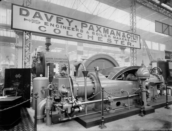
Large Paxman gas engine exhibited at the Franco-British Exhibition of 1908 held at White City, London.
Awarded the Grand Prix, this two-cylinder single-acting engine with opposed cranks had a 9 foot diameter flywheel
and was rated 250 bhp at 160 rpm.
Main Features of the Paxman Gas Engine
Paxman gas engines were all of the horizontal type, built on a substantial cast-iron bedplate and similar in general layout to some of the Company's horizontal stationary steam engines. Working on the Otto four-stroke principle, they were actually described in the Company's 1908 catalogue as '"Paxman" Improved Otto Gas Engines'.
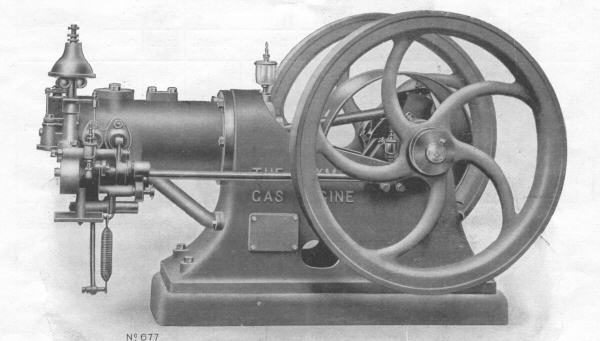
5 bhp gas engine, with tube ignition, for working on town gas (from Pub 517 of 1908).
Cylinder and Valve Gear: The water-jacketed cylinder was fitted with a loose liner made of close-grained cast iron, which was replaceable in the event of damage or excessive wear. The outer end of the liner was free to expand and contract with variations in operating temperature, to minimise stress. The smaller types of engine had a fixed cylinder head with the inlet valve located on the side of the cylinder. On larger types the breech end of the cylinder was removable and the inlet valve was located on top of the cylinder. On all types the exhaust valve was located on the under side of the cylinder.
The inlet and exhaust poppet valves were operated by cams mounted on, and driven by, an open sideshaft. Both inlet and exhaust valves were designed to be easily accessible and removable for maintenance or replacement, as were the valve seats.
Fuels: The engines were designed for running either on town gas or on producer (or suction) gas. Lower down this page is a section which explains the differences between the two types of fuel and how each was produced.
Ignition Arrangements: Engines were fitted with either tube ignition or low-tension magneto ignition. In the 1908 catalogue those engines designed for running on town gas were all offered with tube ignition as standard or, as an option at additional cost, with magneto ignition. All engines designed for running on producer gas were fitted with magneto ignition. By the time of the 1913 catalogue all the Company's gas engines were offered with magneto ignition as standard apart from the three smallest town-gas engines. The arrangements are described in more detail in the section below headed Ignition Arrangements.
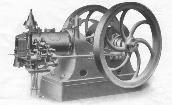
26 bhp gas engine, with magneto ignition, for working with suction gas plant (from Pub 517 of 1908).
Engine Speed Governing: The smallest engine, the 2½ bhp B type/size, was fitted with an inertia governor. All other sizes of engine had a rotary governor, said to operate on a combination of the 'hit and miss' and 'regulation of mixture' principles. (Alex Walford does not believe the governor operated on a 'regulation of mixture' principle. He thinks it must have worked on a quantitative, not a qualitative, principle: varying the quantity of gas fed to the engine, not the proportion of fuel to air.) The rotary governor was adjustable, allowing engine speed to be altered considerably either above or below the normal speed.
Flywheel Arrangements: The smallest engine, the 2½ bhp B type/size, was supplied with a single flywheel. In the 1908 catalogue larger engines were offered with two flywheels, except for those with outputs over 100 bhp which had only one.
In the 1913 catalogue engine sizes C to H (5 bhp to 20 bhp) were offered with two flywheels, and larger engines with a single flywheel, as standard. Where preferred by the customer, some two-flywheel engines could be modified to have a single flywheel and vice-versa, at additional cost. The standard flywheel arrangements were stated to be sufficient for ordinary industrial purposes where a variation in speed of 5% between no load and full load was close enough for satisfactory working. For electric lighting applications engines were fitted with a extra heavy single flywheel of large diameter to maintain greater regularity of running.
Power Outputs: Paxman's 1908 gas engine catalogue offered a range of engines for running on town gas with maximum power outputs from 2.5 bhp (at 300 rpm) up to 47 bhp (at 200 rpm). A note stated that larger size town gas engines, up to 300 bhp, were available on application. In the same catalogue the range of engines offered for working with suction gas plant had maximum outputs from 8 bhp (at 250 rpm) up to 150 bhp (at 160 rpm).
The 1913 catalogue offered a range of town gas engines with maximum power outputs from 2.5 bhp (at 300 rpm) up to 175 bhp (at 160 rpm). Single-cylinder engines offered for working with producer gas had maximum outputs from 8 bhp (at 300 rpm) up to 150 bhp (at 160 rpm). Two-cylinder engines for working with producer gas had maximum outputs from 150 bhp (at 200 rpm) up to 300 bhp (at 160 rpm).
Power outputs, speeds and dimensions of the engines offered in the 1908 and 1913 catalogues are given in Appendix C at the foot of this page.
More information on the construction and features of Paxman gas engines is to be found in Appendix A and Appendix B at the foot of this page. These contain transcripts of the engine descriptions given in the Company's gas engine catalogues of 1908 and 1913 respectively.
Fuels - Town Gas and Producer (Suction) Gas
As explained above, Paxman gas engines were designed for 'working on town gas' or for 'working with suction gas plant'. Suction gas was, in practice, a mixture of producer gas and water gas, with a calorific value only about 20% of that of town gas. Engine power outputs quoted in the company's 1913 catalogue were based on the assumed calorific value of town gas being 700 BThUs per cubic foot, and the approximate calorific value of suction gas being 140 BThUs per cubic foot. 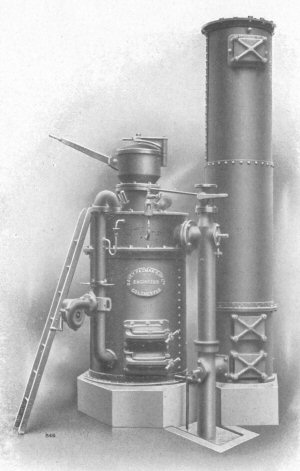 Consequently, engines running on town gas had greater power outputs than equivalent-size engines fuelled by suction gas, as can be seen from the figures given in the 1913 catalogue (see Appendix C).
Town gas, also known as coal gas, was produced by the distillation of bituminous coal. Its main constituents are hydrogen, methane and carbon monoxide. It was the gas generally available for domestic and industrial use in the UK until natural gas became more widely available in the 1970s (at that time often referred to as 'North Sea gas').
In the early Paxman gas engine catalogues the alternative to town (coal) gas is sometimes referred to as suction gas and sometimes as producer gas. Technically there is a difference between suction gas and producer gas.
Producer gas is generated by passing air over hot or incandescent coke which produces a mixture of carbon monoxide and nitrogen (O2 + 4N2 + 2C = 2CO + 4N2). Because of the high proportion of nitrogen in the atmosphere, producer gas contains about 60% nitrogen and therefore has low calorific value. Only the carbon monoxide is combustible, burning with the charge air to form carbon dioxide (2CO + O2 = 2CO2).
Passing steam, rather than air, over hot carbon (such as coke), produces a mixture of both carbon monoxide and hydrogen (H2O + C = CO + H2) known as water gas. This has a higher calorific value than producer gas as both carbon monoxide and hydrogen are combustible, burning with the charge air to produce carbon dioxide and water vapour (CO +H2 + O2 = CO2 + H2O).
Right: A typical Paxman Suction Gas Plant.
In suction gas plants steam was drawn through hot or incandescent coke to produce a better fuel than plain producer gas. In practice such plants probably generated a mixture of producer gas and water gas, rather than purely water gas. The name 'Suction Gas' derived from the fact that the vacuum created in the engine's cylinder on the inlet stroke was used to suck or draw steam and air through the incandescent coals of the gas generator. This was safer than forcing steam or air through the generator under pressure and had other practical advantages. For instance gas production ceased when the engine was stopped or on stand-by.
Paxman designed and manufactured suction gas plants for use with both its own engines and those of other manufacturers. A full explanation of the construction and operation of these plants can be found on the page Suction Gas Producers.
Ignition Arrangements - Hot Tube and Magneto Types
In the 1908 catalogue all engines designed for running on town gas were offered with tube ignition as standard, as were the three smallest town-gas engines advertised in the 1913 catalogue.
The tube ignition arrangement used a metal or porcelain tube, closed at one end. The open end of the tube was fitted into the head of the cylinder in such a way that the inside of the tube communicated with the combustion chamber. Part of the tube's exterior was heated by a small gas flame, similar to that of a bunsen burner, to a cherry red glow. During the compression stroke a charge of fresh gas was compressed up the tube to a point where it was hot enough to ignite. The resulting flame travelled down the tube to ignite the main charge of gas in the combustion chamber.
The simplest form of tube ignition, fitted on the three smallest town-gas engines (sizes B, C, and D), was 'automatic-timed tube ignition'. A refinement of this arrangement, used on Paxman's larger town-gas engines (sizes E and above), was 'mechanically timed tube ignition'. A small valve, the ignition timing valve, operated by a cam, controlled the timing of fresh charges of gas entering the ignition tube. Claimed advantages for mechanically timed tube ignition were economy in gas consumption and the prevention of premature ignition under all conditions of load.
Engines designed for running on suction gas were equipped with a low-tension magneto ignition system. Tube ignition would not have worked satisfactorily because of the relatively poor ignition properties of suction gas compared with town gas. Town gas engines offered in the 1908 catalogue were also available with magneto ignition, instead of tube ignition, at additional cost. By the time of the 1913 catalogue magneto ignition was offered as standard on all engines, except the three smallest town-gas engines for which magneto ignition remained available as an option at additional cost.
The low-tension magneto (magnetoelectric generator) used the magnetic field of a set of permanent magnets to create a low voltage current in a rotating wire coil, the current being supplied to an igniter fitted into the cylinder head. The magneto arrangement did away with the need for a battery or other external power source to supply current to the igniter. The igniter had a fixed point and a movable point within the combustion chamber. The two points were held in contact with each other until the movable point was operated by a trip mechanism to break the circuit and produce a spark.
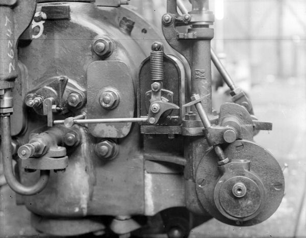
Low tension magneto and igniter on a Paxman gas engine.
In the lower right corner of the picture is the eccentric on the side shaft which operates the trip mechanism.
To the left of the picture is the igniter, its movable point actuated by the horizontal rod in the centre of the picture.
Paxman gas engines with magneto ignition were fitted with 'variable magneto ignition' which allowed the ignition timing to be retarded. Retarding the ignition timing made an engine easier to start and avoided the risk of backfiring. Once the engine was running smoothly, the timing could be advanced to achieve the best fuel economy.
A little point of interest is that the magnetos fitted to Paxman engines before the outbreak of World War 1 were sourced from Bosch in Germany. Paxman was faced with a supply problem when war broke out and it was no longer possible to import equipment from Germany.
Applications
Gas engines were sold for a wide range of industrial applications where a prime mover was required to drive other machinery. In many of these applications minor variations in crankshaft speed were not critical, and a 'hit and miss' governor was adequate. For others, such as generating electricity and textile mill driving where speed variations needed to be more tightly controlled, the Company offered the Paxman patent throttle governor and valvegear. This controlled the amount of opening given to the gas valve thus determining the strength of the mixture delivered to the engine and the power output. Electrical power generation was an important application and extra heavy large diameter flywheels were available also to achieve more constant crankshaft speeds.
A very different application was laundry work. In 1926 the Company produced a catalogue (No 741) of power plant for laundries, a growing market at the time. Although dealing primarily with steam equipment such as boilers, it also offered a range of gas engines little changed from that in the 1913 catalogue (for the latter see Appendix C).
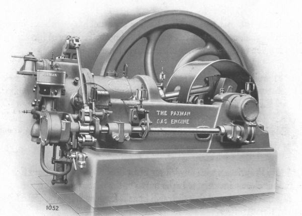
Type L gas engine, with magneto ignition (as shown in a post-World War One catalogue).
Sales of Paxman Gas Engines
Paxman commenced manufacture of gas engines in 1904. Records of early sales are sketchy. Order entries for gas engines, and the very similar benzine engines, do not appear in the surviving Paxman copy order books until January 1911. At this point there is a note in the surviving copy order book saying, "As it has been decided to use only one Order Book for all orders "Steam" and "Gas", the number of "Gas" Orders (1016) has been added to the "steam", to arrive at a total thus:- Engines and Boilers 9794, Gas 1016, (total) 10,810. The Order Nos will therefore run consecutively from O No 10,811. Frank H Cansdale, Order Clerk."
It seems fair to assume that the 1,061 "Gas" orders received from 1904 to the end of 1910 included orders for suction gas plants and benzine engines as well as those for gas engines. It is thought that relatively few benzine engines were sold during this period. Paxman's development of its gas engines was rapid, the first being built in 1904. In Steam and the Road to Glory Andrew Phillips says that over fifty gas engine orders were received in 1905, and 85 in 1906. (3) In 1911, the first year for which we have order records, a large proportion of gas engine sales were to overseas customers.
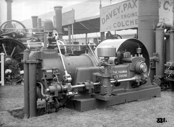
A large Paxman gas engine exhibited at the 1911 Royal Agricultural Society Show, held at Norwich.
A surviving Paxman copy order book records that three different gas engines were built for this show: -
a town gas engine (Type G), and two suction gas engines (Types K and Q), each with a producer plant (Order Nos 10975/6/7).
The company continued to build gas engines for about twenty five years. Orders fell away sharply after 1920 with only occasional orders being received after that date, mostly for export. By this time the oil engine had become the favoured prime mover for the power range covered by gas engines. The final order Paxman received for a gas engine appears to have been received in April 1929. This was Order Number 17214, for an 'L' type engine for the Levant Iron & Machinery Co, sent to Constantinople on 27th April 1929.
Surviving Paxman Gas Engines
Identifying Paxman gas engines: For a long time I had assumed, incorrectly, that the number of a Paxman gas engine would be stamped on one end of the crankshaft, as was the company's practice on its portable steam engines of the same period.
On a Paxman gas engine the (usually five-digit) number should be found stamped on a machined surface either on the cylinder head or on the cylinder casting near the cylinder head. I now have photographic evidence this is true in the cases of engine Nos 17947 and 18500 described below. 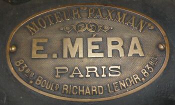 It would be interesting to receive confirmation that this is true also in the case of the one owned by Philippe Le Roch described below.
I am aware of five surviving examples of Paxman gas engines. Three of these are in France which is not surprising as a good number of Paxman gas engines were sent there. Details of gas engine orders prior to 1911 are not available. From 1911 up to the start of World War One virtually all Paxman gas engines for France were sold through one agent, Emil Méra of Boulevard Richard Lenoir, Paris. In 1911 Emil Méra placed orders for 14 engines, in 1912 for 12 engines, in 1913 for 19 engines, and in 1914 for 6 engines. Thereafter he ordered 3 during 1916 and 4 during 1917. Sadly surviving Paxman records do not show the names of Méra's customers who bought these engines.
Emil Méra agent's plate on No 17947.
 No 17947 This engine and its suction gas plant were built under Paxman Order No 11917, dated 15th October 1912. The surviving copy Order Book describes it as '21/24 BHP Suction Gas Plant', size X, from which it is clear the engine was supplied complete with suction gas producer. In Paxman's March 1913 catalogue, Gas Engines and Suction Gas Producers (Publication No 650), the design speed is given as 250 rpm. A surviving copy of this publication has a note in pencil that the size X engine had a 9¾ inch bore and 15 inch stroke. The engine was sold through Paxman's French agent, Emil Méra, and dispatched from the Colchester factory on 5th June 1913.
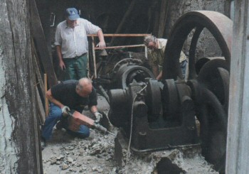
Right: Engine being removed from artisan's workshop to go into preservation.
A French news sheet, Le Moteur Fixe No 39, dated December 2010, carried a page of photographs and a little information about the engine which was originally installed in the ALSTOM factory at Belfort in eastern France, about 12 miles from the Swiss border. It was bought later (in 1928?) by an artisan to drive an alternator to produce power for the (woodworking?) machinery in his workshop. In the news sheet the flywheel's diameter was stated to be 2 metres.
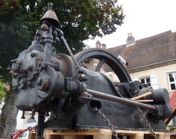 As at 2016 the owner of No 17947 was Mr Denis Brand, an engine enthusiast living in Montigny-lès-Vesoul, Haute-Saône (about 30 miles west of Belfort), who owned a collection of more than 40 stationary engines. In his email to me in January 2016 he told me the plan was to install the gas engine on the body of a 1945 Citroen truck for display at engine rallies. Consideration was being given to restoring the producer gas plant.
Left: Engine loaded on a lorry after removal from the artisan's workshop.
No 18500 Many years ago (the now late) Alex Walford visited and photographed this engine in Lower Normandy, Northern France. He showed me the photograph reproduced below, taken when the engine was in working order, running on producer gas from a gas generator on the site.
Some years ago I came across a website that said the engine was installed in 1912 at the Château de la Mare, Coutances, as part of an electrification project. In the light of information received recently (September 2021) we believe this is incorrect. According to the current owner of the chateau, electric lighting was installed in the chateau in 1912; this would be the electrification project referred to. (Sadly, the once imposing chateau is now a ruin). We believe the Paxman gas engine was installed in late 1913, not in the chateau but in a sawmill, 'La Sciérie de la Mare', situated a few hundred metres from the chateau. A surviving Paxman copy order book shows that the engine was not ordered until 3rd November 1913 and was despatched from the factory about three weeks later, on 25th November. Records of the engine's history held by the Musée des Fours à Chaux at Regnéville-sur-Mer show that for many years it was used in a sawmill to drive saws and other machinery. That is consistent with the words 'Scierie de la Mare' on the large board in the photograph below.
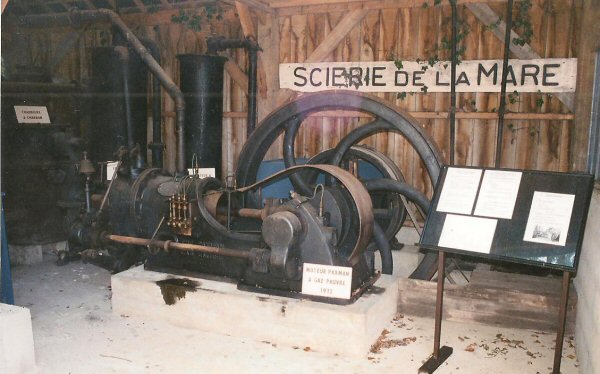
Photograph of No 18500 taken when the engine was on public display (before 1989) at Regnéville.
The engine was bought by the Manche département on 15th May 1987 for ₣11,488 French Francs (equivalent to about €3,000 (Euros) in 2021), from Georges Bellier. It was then put on display at the Musée des Fours à Chaux (Lime Kilns Museum) de Regnéville, at Regnéville-sur-Mer, a small village on the west coast of Lower Normandy's Cotentin peninsula, west of Saint-Lô and near Coutances.
After I saw a report in December 2010 that the engine was at this museum, I and others made inquiries, over a number of years, to try to find out if the engine was still at Regnéville, where it was if it had been moved from there, and what its number was. Our inquiries proved fruitless. Then, on 23rd September 2021, an email was received from Philippe Castel, a French engine enthusiast. With the help of Jean-Yves Cocaign, the curator of the museum at Regnéville, Philippe had been to see the engine the previous day. The engine was not on public display but in the museum's reserve collection where it has been stored since 1989. Philippe and Jean-Yves successfully located the engine's number. The stamped number, confirmed by a photograph emailed to me by Philippe, is 18500.
Having the engine's number enabled me to look up details of the order in a surviving Paxman copy order book. This shows that No 18500 was made against Paxman Order No 12470, entered on 3rd November 1913. The order was for a 28/31 BHP Gas Engine, size Y, and was placed by E Méra. The engine was despatched to France from the Colchester factory on 25th November 1913. In a photograph sent by Philippe one can see the engine carries an E Méra agent's plate of the same design as that on engine No 17947 (see above).
As shown in the third table in Appendix C at the foot of this page, the size Y's cylinder is 10¾ inch bore and 16 inch stroke. The engine's speed is 240 rpm. Running on producer gas the working load is 28 BHP and the maximum load 31 BHP.
Philippe reported that the engine appears to be complete and in reasonable condition. There is some surface corrosion present which is not surprising as the engine has been in store for over 30 years. It is sheltered from the elements.
In its collection the museum appears to have the parts not for one but for two suction gas plants for the engine. These are a coal-fired gas generator, a wood-fired gas generator and two scrubbers, the latter for cleaning and cooling the gases before they pass to the engine.
The museum has three information sheets that trace the history of the engine and its operation in the sawmill which ran from 1912 to 1978. At the sawmill the engine was used to drive a log saw, a table saw, a grinding machine and several small machines. The engine also drove a 'ram' type of pump to supply water from a well to the chateau and, finally, a generator to supply electricity to the engine operator's house.
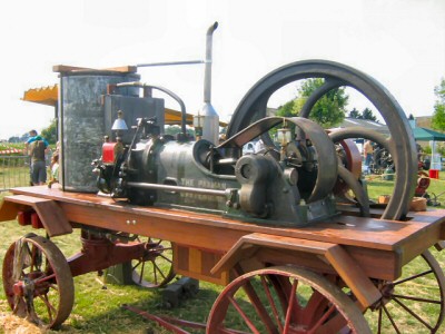 No ????? The restored Paxman gas engine pictured right was seen at an engine rally in France, perhaps near Paris.
A YouTube video (uploaded in December 2008) of this engine running can be viewed at https://www.youtube.com/watch?gl=FR&hl=fr&v=T-fwQZkPU04 Clearly visible in the clip is the eccentric on the side shaft operating the trip mechanism for the low tension magneto.
As at November 2021 the engine is owned by Philippe Le Roch and is still in running order. It was bought by Philippe in the town of Angerville (91670) and comes from a water tower. From lettering on the main casting one assumes it was originally built as a gas engine. Later fitted with a carburetor, it has been converted to run on petrol. Unfortunately at some time the engine's number has been filed off so there is no way of checking its details in surviving order records.
The magneto fitted to this engine was made by Hill Brothers of Bristol. If the magneto is the one originally fitted, this would suggest the engine was built after 1914. Up to 1914 Paxman is understood to have fitted magnetos by Bosch of Germany. These were no longer available to Paxman after the outbreak of World War 1 and the company had to look for an alternative supplier.
The flywheel is 4' 8" diameter. The bore and stroke are 5¾" and 11". This suggests it is a size D, designed to run at 280 rpm.
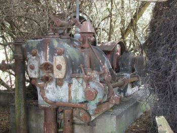 No 18540 This engine was found in a derelict state, but with its original gas producer, in autumn 2011 (near Blenheim?) in South Island, New Zealand. It is a size K engine of 11½" bore x 16" stroke, with a power rating of 32/36 bhp when running on producer gas. The 6" diameter flywheel has an 8" face.
Gas Engine No 18540 as found at Marshlands Farm before removal to Christchurch.
The engine was found at Marshlands Farm where it was installed to pump water from a large swamp where flax was grown and harvested. It is thought probable the engine was stopped when the flax mill closed. A surviving Paxman copy order book shows the engine was ordered on 15th December 1913 and despatched to Wellington a month later. The customer is recorded in the order book as the Pooley Hall Colliery Co which we know was at Polesworth, near Tamworth in England. The Colliery Year Book and Coal Trades Directory of 1923 shows the Chairman of the Pooley Hall Colliery Co as Colonel D'Arcy Chaytor and another of the Directors as Major-General Sir Edward Chaytor of 3 Clermont Terrace, Wellington, New Zealand. It is known the Chaytor family has owned Marshlands Farm for over a hundred years so it can safely be assumed the engine was bought by the Colliery Co for Sir Edward or another member of the Chaytor family who had emigrated from England to New Zealand.
When acquired in November 2011 by Stephen Hendrie, the engine and gas producer were still in the remains of the shed where they were set up. As can be seen in the photograph here, a number of parts had been removed from the engine before it was rediscovered. Fortunately, these have been recovered. Stephen reported that the engine was in good condition, although the oilers and magneto were missing. The engine and its gas producer were moved to safe storage at Christchurch where Stephen hoped to restore them in time for their 100th birthday.
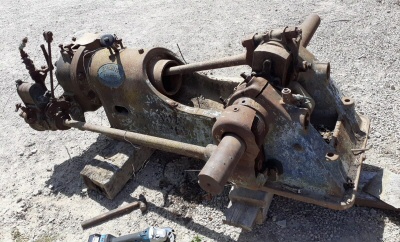 No ????? in Mallorca (known as Majorca in the UK) As can be seen in the picture to the right, this engine was in a very poor state in July 2020 when acquired by Jaime (English: James) Pastor in Mallorca. Despite very careful examination it has not been possible to find any number on the engine so records cannot be checked for its date of manufacture and original purchaser. Checking records might not have been possible in any case as surviving records of Paxman gas engine orders before January 1911 are very sketchy or non-existent.
Right: The engine as at July 2020. Photo © Jaime Pastor 2020
The engine was found in Sa Pobla, a small municipality in the north of the island. (The area is known for growing potatoes which are exported to several countries.) For the previous fifty years or so the engine was located in a forest where it was originally used to drive (by belt) a reciprocating water pump. Found with the engine were parts of the old gas producer plant but, sadly, these were very badly corroded. In Mallorca the usual fuel for all gas producers was almond shells.
From the dimensions of the flywheel the engine was identified as a Type G. This was confirmed with checks of the engine's bore and stroke which are 7 inches x 14 inches.
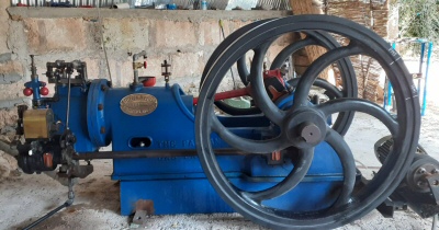 Jaime, with the help of a friend, restored the engine to working order in a remarkably short time. Jaime is a retired lathe and milling machine operator. With his valuable knowledge and skills he was able to make missing parts such as the valve housing and rocker gear. Work on restoration commenced in July 2020. By mid-December 2020 the engine, which has been fitted with a carburettor so that it can run on petrol, was back in working order. A remarkable achievement.
Left: The restored engine as at February 2021. Photo © Jaime Pastor 2021
Jaime is a collector of agricultural implements and the gas engine is now part of his collection at Maria de la Salut in the centre of Mallorca.
My thanks to Joseph Alemany in Mallorca who was most helpful in provided information and images of the engine as the restoration project progressed.
Appendix A
General description of Paxman gas engines as appearing in Paxman Publication No 517 of 1908:
The "Paxman" Gas Engines.
THESE ENGINES HAVE BEEN CAREFULLY DESIGNED WITH A VIEW TO OBTAINING THE GREATEST ECONOMY IN THE CONSUMPTION OF GAS, TOGETHER WITH RELIABILITY OF WORKING.
Due Proportion and Accessibility of Parts. — Particular attention has been paid to the due proportion of the various parts of the Engines, and to their accessibility for inspection.
Bed. — The bed is a single casting of rigid and massive design, without being unnecessarily heavy, and is accurately bored to receive cylinder and crankshaft bearings, and planed for the sideshaft bracket.
Bearings. — Crankshaft bearings are of best gun metal of ample size and accurately machined, but on sizes II. and upwards the bearings are of cast iron with our special antifriction lining and fitted with self oiling chain lubrication.
Cylinders. — The cylinder is fitted with a loose liner, cast of a special hard mixture, so arranged that the outer end is free to expand and contract with the varying temperature of explosion. The liner is of special hard mixture, and so arranged as to be readily renewable in the event of wear or damage.
Valves. — All valves are fitted in loose seatings which fit in accurately bored and ground recesses in the cylinder so that no asbestos joints are required. By this means the valves and seatings can be readily removed for examination if required.
The valves are of steel and very durable.
Piston. — Of the best close grained cast iron, with at least four loose rings, easily renewable when necessary.
Flywheels. — All Engines above the 2½ h.p. size are provided with two flywheels, except those of over 100 h.p., which only have one.
Connecting Rods. — The Connecting Rods are steel forgings, accurately machined and fitted with heavy brasses, having large wearing surfaces. On the larger sizes the connecting rods are fitted with cast steel shells lined with our special antifriction metal.
Gear Wheels. — The wheels for actuating the side shaft are machine cut and run in an enclosed oil bath.
Sideshaft. — Of mild steel, turned, polished and fitted with bearings of ample length.
Governing. — The speed is controlled by a very sensitive rotary governor driven by machine cut gears, and the gas consumption is regulated strictly in accordance with the power taken from the engine. An arrangement is provided on the governors whereby the speed may be altered considerably either above or below the normal.
Note. — The 2½ h.p. engines are fitted with an inertia governor.
Crankshafts. — The crankshafts are of forged steel, the balance weights being attached directly to the webs of the crank, and not, as in some instances, cast in the rim of the flywheels.
By our method the engines run much more regularly, and unequal strains on the rims of the flywheels are avoided.
Ignition for Producer Gas. — The engine is fitted with electric ignition, worked by a magneto machine, so that no battery is required. Paxman's patent timing apparatus is fitted so that the timing of the spark can be adjusted so as to facilitate starting.
Ignition for Town Gas. — Engines of the E type and above are fitted with an improved ignition timing valve which ensures economy in gas consumption and prevents premature ignition under all conditions of load. The engines are fitted with either porcelain or metal tubes. Magneto ignition can be fitted to town gas engines at an extra charge.
Anti-Fluctuator. — Each town gas engine is provided with a gas bag, fitted into a cast iron case with an anti-fluctuating valve, whereby the gas pressure supplied to the engine is kept constant.
Lubrication. — Careful attention has been paid to the lubrication of the different parts, and the crankpin is fitted with a ring oiler, so that it is not necessary to stop the engine to replenish the big end connecting rod.
Self-Starter. — If required, with the larger engines, we can supply a compressed air self-starter, which renders the starting of the engines extremely certain and simple.
Exhaust Silencer, Pulley and Set of Wrenches are provided with each engine.
Air Silencer. — An inlet air silencer is also supplied with the larger size engines.
Spare Parts. — The following spare parts are supplied with each engine: —
1 complete set of springs and 1 piston ring, and spare ignition tube on town gas engine.
Renewals. — All parts are made to templates, so that in case of breakage or wear of any part, it can be immediately renewed out of our stock.
Note. — Davey, Paxman, Ltd. reserve to themselves the right to alter the above specification without notice, but in no case will any alteration be made which does not effect an improvement.
Appendix B — Paxman Publication No 650, March 1913
The following transcript of the general description of Paxman gas engines, given in Publication No 650, does not include the section describing the Company's Suction Gas Producers. A transcript of that section can be viewed on the page Paxman Suction Gas Producers.
The illustrations in the original publication are not included in this transcript.
No. 650
Gas Engines
AND
Suction Gas Producers
Manufactured by
Davey, Paxman & Co. Ltd.
COLCHESTER, England.
| London Office : 78 QUEEN VICTORIA STREET, E.C. Telegraphic Address : "Paxman, Cannon, London." Telephone : No. 697 Bank. |
Head Office & Works : COLCHESTER. Telegraphic Address : "Paxman, Colchester." Telephone : No.52. |
Codes used :
A B C (4th and 5th), A1, Engineering (1st and 2nd), Lieber's,
Moreing & Neal, and Private Codes.
MARCH, 1913
Foreword.
WE think it not amiss, in presenting this latest Catalogue of our Gas Engines and Suction Gas Producers to our clients, to say a few prefatory words as to our unique position as manufacturers of Steam and Internal-combustion Engines. We have been builders of steam engines and boilers for over half a century, both high and slow-speed, small and large engines, and of types ranging from the simplest of slide-valve engines to the latest and most economical of drop-valve engines on the market to-day, and we can confidently assert that our productions have never been surpassed as regards economy and reliability.
It is unnecessary to enlarge upon the fact that never have the advances made in the design of internal-combustion engines been more marked than since their manufacture was taken up by firms who, like ourselves, have had great previous experience in designing and building high-class steam engines. Our unrivalled position in both lines enables us to advise clients without bias as to the most suitable motive power to instal, considering all the circumstances of the case. We make no extravagant claims for either Steam or Gas, as we recognise that either power presents certain advantages under certain specified conditions. In approaching us, therefore, clients can rest assured that they will benefit from such a large and varied experience as is probably possessed by no other firm.
And finally a word or two respecting the vexed question of price. We admit frankly that our engines are not the lowest priced it is possible to obtain — a study of our high-class design will show that this is not possible! The real economy, however, of an engine does not consist in its first cost, but rather in Reliability, Durability, Low Fuel Consumption, and the Saving in Labour which can only be obtained by installing a thoroughly high-class plant. The cheapest engine in first cost will invariably prove the dearest in the long run. It has been our constant policy and desire, whether with our Gas or Steam Engines, to produce the most reliable and most economical type possible, and in this we claim we have succeeded.
This catalogue cancels all preceding editions.
DAVEY, PAXMAN & CO. Ltd.
Special Features of the Paxman Gas Engines :
| Reliability. Low fuel consumption. Highest-class workmanship. Improved designs. Easy starting. Close governing. Chain oiling on all main bearings. Positive lubrication to piston pin. Continuous lubrication to crankpin. |
Crankshafts machined from the solid forging. Balanced cranks fitted to all engines. Patent magneto ignition, with timing device, fitted to all engines. All valves easily accessible and removable. All gear wheels machine-cut. Expansion box provided with all plants. Self-starter to large sized engines. |
Guarantee.
In lieu of any warranty implied by law, we undertake to repair or replace any part which within a period not exceeding twelve mouths from delivery may prove to be defective through bad material or workmanship, fair wear and tear being, of course, excepted; the carriage on such parts being paid by the customer. But the plants are supplied on the condition that we shall not be liable for any losses incurred through stoppages, nor for any direct or consequential damages arising from such defect, and subject to oil approved by us having been used for the plant. Delivery of such replacements in the case of engines abroad will be made f.o.b. nearest English shipping port.
The Paxman Gas Engines.
Design. The design of the Paxman Gas Engines is being constantly revised, so as to embody the latest improvements ; all illustrations, therefore, given in this catalogue must not be taken as binding in detail. Particular attention is paid to the accessibility of the different parts in all sizes, and in designing our engines we have never lost sight of the fact that they should be of so simple a character that they can be properly looked after by the average engine attendant.
The Bed. The bedplate is an extremely massive casting, extending beneath the cylinder as far back as the combustion chamber, thus supporting the cylinder along the whole working length, and ensuring perfect freedom from vibration and movement. It is well ribbed, and an oil trough is formed all round the base to prevent oil reaching the foundations. This casting is accurately machined to receive the cylinder liner, crankshaft and sideshaft bearings. The three very small sizes are built with overhung cylinder.
Cylinder. The cylinder is fitted with a loose liner, made of specially hard, close-grained cast-iron, so arranged that the outer end is free to expand and contract with the varying temperature of explosion. Except in the smallest sizes, the breech end is also removable, and separate from both cylinder jacket and liner, and has been designed to overcome what was hitherto a weakness in gas-engine design. In this construction, the inner and outer walls are tied by the exhaust and inlet passages, stout ribs supporting the back of the combustion chamber, by which arrangement the breech end is relieved of all internal casting strains. The inner and outer walls are also connected by a number of substantial steel bolts, the whole arrangement being sufficiently elastic to accommodate itself to the working strains due to pressure and the varying temperature of explosion.
The water jacket is provided with large inspection doors, through which any deposit may be removed.
It will be seen from the small illustration at the side (not shown here) that all valves in the Paxman design open directly into the combustion chamber, and not into pockets bolted to or cast on the cylinder. In other engines designed with pockets in the cylinder, it is extremely difficult to ensure that the exhaust gases are completely expelled at the end of the exhaust stroke ; whereas with our design there are absolutely no pockets in which the flame can lurk, and the cylinder is consequently completely and thoroughly scavenged ; in fact, it is shown by the indicator that there is a slight vacuum at the end of each exhaust stroke, which ensures that a new charge entering the cylinder is not adulterated with the products of the previous explosion. More power is thus obtainable from the engine, and one of the most fruitful causes of pre-ignition is done away with.
Bearings. The crankshaft bearings are of the best gun-metal, of ample size, and accurately machined ; but on size "J" and upwards the shells for the bearings are of cast iron, lined with special anti-friction metal. The crankshaft bearings are so designed that the thrust is taken by the frame. All bearings are adjustable.
Piston. The piston is of the best close-grained hematite iron, with at least four loose rings, easily renewable when necessary.
Valves. All valves work in loose seatings, which fit into accurately bored and ground recesses in the combustion chamber so that no jointing material is required, and the seatings can be readily removed by simply unscrewing a couple of nuts. It will be seen from the illustration of the cylinder that the valves are very accessible. The exhaust valve is placed at the bottom of the combustion chamber, and can be easily examined or removed.
Pulley. All engines of the industrial type are provided with suitable driving pulley. Engines of the electric-lighting type are only supplied with pulley when this is specially ordered, but space for our standard size of pulley is provided on the shaft between the flywheel and the outer bearing.
Flywheels. Engines from size "C" to "H" inclusive are stocked with two flywheels. Engines from size "J" to "T" inclusive are stocked with single flywheel and outer bearing. We can supply the smaller engines from size "E" to "H" inclusive with single flywheel and outer bearing at an extra charge, and in the case of sizes "J" to "K" inclusive we can modify our standard arrangement by fitting these engines with two flywheels. These flywheels are sufficient for ordinary industrial purposes, where a variation in speed of 5% between no load and full load is sufficiently close regulation for satisfactory working.
Engines for "Electric lighting" are fitted with one extra heavy flywheel of large diameter (to ensure regularity of running), extended crankshaft and outer bearing.
On page 33 will be found diagrams giving the different possible variations of flywheel and pulley arrangements. It should be borne in mind, however, that any deviation from our standard practice is liable to delay delivery.
Connecting Rods. These are steel forgings, accurately machined, and finished bright all over, fitted with heavy bearings having large wearing surfaces. Except in the smallest sizes, the large-end bearings are lined with special anti-friction metal. The small-end bearings of all sizes are of best gun-metal.
Gear Wheels. The gear wheels for actuating the sideshaft and governor are machine-cut, and run in enclosed oil baths.
Sideshaft. The sideshaft is of mild steel, finished bright, and supported in bearings of ample length. The cams are all milled to standard pattern.
Governing. The speed is controlled by a very sensitive rotary governor, on a combination of the "hit and miss" and "regulation of mixture" principles, whereby the gas consumption is regulated strictly in accordance with the power taken from the engine. The governor is driven by machine-cut gears, and an arrangement is provided whereby the speed may be altered considerably either above or below the normal. The small size "B" engine is fitted with inertia governor.
Crankshaft. The crankshaft is of Siemens-Martin steel, machined from the solid forging, and finished bright, the balance weights being securely attached to the rims of the cranks. By this method, the engines run much more regularly, and unequal strains on the rims of the flywheels are avoided.
Ignition. The ignition of these engines is effected by means of a magneto, fitted with a timing device, which can be adjusted while the engine is running. This enables the time of ignition to be retarded at starting, thus avoiding any possible risk of a back-fire ; whilst as soon as the engine is fairly under way, the point of ignition can be advanced, so as to give the early firing which is required to obtain the full economy from producer gas. Duplicate ignition is fitted to all engines of size "Q" and upwards at an extra charge.
Lubrication. The most careful attention has been paid to the lubrication of the working parts of the engines. The crankshaft and sideshaft bearings of all engines from size "E" to "T" inclusive are fitted with self-oiling chain lubrication. The lubrication troughs for these bearings are designed so as to be easily cleaned, and inspection doors are provided.
Forced lubrication is fitted to the cylinder on all engines of size "Y" and upwards. The crankpin bearing of all engines is provided with dust-proof centrifugal ring-oiler, as (not here) shown in the small illustration at side. The piston pin is positively lubricated by means of an adjustable sight-feed lubricator fixed on the cylinder, which delivers oil to a trough attached to the piston, whence it flows directly on to the pin.
Starting Apparatus. With engines of size "Y" and upwards, a starter is necessary. We recommend the compressed air starter, especially for the larger engines, on account of its reliability, and the ease with which it can be used, enabling our gas engines to be got under way with the same certainty as a steam engine. For the smaller engines, a pump starter using petrol, benzine, or town gas is often supplied. For further particulars of starters, see page 31.
Anti-Fluctuator. Each town-gas engine of our make is provided with a gas bag, fitted into a cast-iron case, with an anti-fluctuating valve, whereby the pressure of gas supplied to the engine is kept constant. This prevents pulsation in the gas main when the engine is working, and the neighbouring lights are not affected.
Exhaust Silencer and Set of Spanners are provided with each engine.
Air Silencer. An air silencer is provided with size "E" engine and upwards.
Spare Parts. The following spare parts are supplied with each engine : One complete set of springs, one piston ring, and one tool for grinding valves.
Renewals. All parts are made to templates, so that in the case of breakage or wear of any part it can be immediately renewed from stock if the engine number is quoted.
Expansion Box. An expansion box is provided between the generator and engine of all suction gas plants.
Power. The powers given on pages 15 to 21 for town-gas engines are on the assumption that gas of a calorific value of 700 British Thermal Units per cubic foot is used. If engines of size "E" and upwards are required to run on town gas, add the code word Raasegel. The powers for suction gas engines given on pages 17 to 23 are the B.H.P. obtainable when anthracite coal is used in the producer, giving gas of an approximate calorific value of 140 British Thermal Units per cubic foot on the lower scale, temperature 60° Fahr. and 30" Hg. When coke is used as fuel, it is advisable to allow for a reduction of power varying from 5% to 10%, though with good coke and careful stoking it is possible to obtain the powers given in this catalogue. When plants are intended to be installed at any considerable height above sea level, the B.H.P. developed by the engine will be reduced by about 4% per 1000 feet altitude.
Note. The foregoing description of our gas engines, and the following description of our suction gas plants, are liable to alteration from time to time in consequence of improvements which we are always striving to effect.
Paxman Gas Engines
With Throttle Governor.
In the case of engines intended for electric lighting, textile mill driving, and other purposes for which the utmost regularity of running is essential, with a low cyclic irregularity, it is advisable to adopt some different system of governing to the well-known "hit and miss" type.
The Paxman patent throttle governor and valve gear has been designed to control the amount of opening given to the gas valve, thus determining the strength of the mixture delivered to the engine, and consequently the power developed. With this system of governing, an impulse is given to the engine every other revolution, and there are no cut-out cycles, as in the case of the "hit and miss" system ; a more uniform turning movement is therefore obtained, and a steady draught maintained through the generator.
The regulation of the strength of the mixture, according to the load carried by the engine, is known as qualitative governing. By our arrangement, the governor can vary the opening of the gas valve from nothing to the maximum lift.
The bed is of extremely massive design, arranged to support the whole length of the cylinder, and an oil trough is formed all round this to prevent oil reaching the foundations.
All engines have single "industrial" flywheel, extended crankshaft, and outer bearing. The crankshaft and sideshaft have chain-lubricated bearings.
Forced sight-feed lubrication is provided for the cylinder by means of an oil pump. Continuous lubrication is fitted to the crankpin, as previously described.
The starting of these engines is automatic, a cam on the sideshaft being used to actuate the starting valve at the right moment. This is, as will readily be seen, a great advance on the usual method of fitting a hand-operated lever, for unless the attendant is very careful he does not make full use of the air pressure, and may possibly allow the air to enter the cylinder on the wrong stroke.
Self-Starters.
Our Gas Engines up to and including size "X" can easily be started by hand by turning the flywheel. There should also be no difficulty in starting sizes "Y" to "N" by hand whenever this is necessary, but for convenience we strongly recommend our clients to adopt a self-starter for all engines from size "Y" upwards. In the case of engines from size "0" upwards, it is hardly practicable to start by hand, and some self-starting device is indispensable ; some means should also be provided for charging the pressure receiver prior to the first start, or in the event of the pressure in the receiver being lost accidentally.
High-Pressure Type. We make two kinds of high-pressure starters. (1) The "Power-driven" self-starter, which consists of a compressor driven direct by either a small town-gas or oil engine or electric motor, and which we recommend for large engines. If required, the fan for blowing up the producer fire can also be driven from the flywheel of the starting engine. (2) The "Belt-driven" self-starter, which consists of an independent air pump, which can be either actuated by hand or driven by belt from the engine or any suitable pulley, provision being made for either, as will be seen from the illustration over-leaf.
The Receiver for both types is of ample size, and is provided with stop valve, relief valve, and pressure gauge.
Low-Pressure Type. The low-pressure starter consists of a small hand-pump fitted on the breech end of the engine. It is worked by a lever, by means of which a charge of petrol, benzine, or town gas and air is pumped into the working cylinder ; the pressure moves the piston, and thereby trips the magneto, the resulting explosion driving the engine round for three or four revolutions, after which it runs in the ordinary way. This is a reliable starter, and much cheaper than the high-pressure type.
Appendix C — Power Outputs, Speeds and Dimensions
Paxman's May 1908 gas engine catalogue (Publication No 517), offered two ranges of engine, one for working on town gas and the other for working with suction gas plant. Specifications shown in the 1908 catalogue include the following:
| Paxman Improved Otto Gas Engines for Working on Town Gas | ||||||||
|---|---|---|---|---|---|---|---|---|
| Type | Maximum B.H.P. | Revs per minute | Flywheel | Pulley | Space | |||
| Diam. | Width | Diam. | Width | Length | Breadth | |||
| B | 2.5 | 300 | 2' 5½" | 4½" | 8" | 6" | 4' 6" | 2' 5.5/8" |
| C | 5 | 280 | 3' 0" | 4½" | 12" | 6" | 5' 11½" | 3' 3" |
| D | 7.75 | 260 | 3' 3" | 4½" | 14" | 8" | 6' 3¾" | 3' 6" |
| E | 9.5 | 250 | 3' 7½" | 4¾" | 18" | 10" | 7' 5.5/8" | 4' 1" |
| F | 12 | 250 | 4' 3" | 4¾" | 24" | 10" | 7' 9.5/8" | 4' 1" |
| G | 15.5 | 250 | 4' 4½" | 5" | 27" | 10" | 8' 1¼" | 4' 10.1/8" |
| H | 18 | 240 | 4' 8" | 5" | 27" | 10" | 8' 3¾" | 4' 10.1/8" |
| I | 20 | 230 | 4' 9" | 5½" | 34" | 10" | 8' 8.7/8" | 5' 2¼" |
| II | 24 | 220 | 5' 0" | 6" | 36" | 11" | 8' 10" | 5' 2¼" |
| III | 30 | 220 | 5' 2" | 7" | 36" | 11" | 9' 9" | 5' 5" |
| K | 35 | 220 | 5' 6" | 7" | 42" | 12" | 9' 10.1/8" | 5' 6¼" |
| L | 47 | 200 | 5' 6" | 7" | 45" | 14" | 10' 6" | 6' 0" |
| Larger size town gas engines up to 300 B.H.P. on application. | ||||||||
| Paxman Improved Otto Gas Engines for Working with Suction Gas Plant | |||||||||
|---|---|---|---|---|---|---|---|---|---|
| Type | Working Load (B.H.P.) | Maximum Load (B.H.P.) | Revs per minute | Flywheel | Pulley | Space | |||
| Diam. | Width | Diam. | Width | Length | Breadth | ||||
| E | 7 | 8 | 250 | 3' 7½" | 4¾" | 18" | 10" | 7' 5.5/8" | 4' 1" |
| F | 8½ | 9½ | 250 | 4' 3" | 4¾" | 24" | 10" | 7' 9.5/8" | 4' 1" |
| G | 11 | 12 | 250 | 4' 4½" | 5" | 27" | 10" | 8' 1¼" | 4' 10.1/8" |
| H | 12½ | 14 | 240 | 4' 8" | 5" | 27" | 10" | 8' 3¾" | 4' 10.1/8" |
| I | 15 | 17 | 230 | 4' 9" | 5½" | 34" | 10" | 8' 8.7/8" | 5' 2¼" |
| II | 18 | 20 | 220 | 5' 0" | 6" | 36" | 11" | 8' 10" | 5' 2¼" |
| III | 23 | 26 | 220 | 5' 2" | 7" | 36" | 11" | 9' 9" | 5' 5" |
| K | 28 | 30 | 220 | 5' 6" | 7" | 42" | 12" | 9' 10.1/8" | 5' 6¼" |
| L | 36 | 40 | 200 | 5' 6" | 7" | 45" | 14" | 10' 6" | 6' 0" |
| M | 45 | 50 | 190 | 6' 0" | 7¾" | 48" | 17" | 11' 2.5/8" | 6' 8¼" |
| N | 54 | 58 | 180 | 7' 0" | 8" | 52" | 19" | 11' 10" | 7' 0" |
| O | 62 | 68 | 180 | 7' 0" | 8" | 54" | 20" | 12' 6" | 7' 2" |
| P | 75 | 85 | 180 | 7' 3" | 8½" | 60" | 21" | 14' 6" | 8' 4" |
| Q | 88 | 100 | 180 | 7' 3" | 9½" | 72" | 24" | 15' 2" | 8' 7" |
| S | 115 | 125 | 170 | 9' 0" | 13½" | 78" | 26" | 16' 9" | 11' 9" |
| T | 135 | 150 | 160 | 9' 0" | 15½" | 84" | 29" | 17' 9" | 12' 6" |
Paxman's March 1913 catalogue, Gas Engines and Suction Gas Producers (Publication No 650), offered twenty different sizes of single-cylinder engine with maximum power outputs ranging from 2.5 bhp to 175 bhp for those running on town gas, and from 8 bhp to 150 bhp for those running on producer gas. Two cylinder coupled versions of the six largest single-cylinder producer gas types were also offered with power outputs ranging from 150 bhp to 300 bhp.
Engine specifications given in Publication No 650 are shown in the table below. Bore and stroke are not quoted in the catalogue but were pencilled in the margin of the copy from which the other figures were taken.
| Size | Bore & Stroke | Speed (RPM) | Town Gas Max Load (BHP) | Producer Gas Max Load (BHP) | Producer Gas Working Load (BHP) |
|---|---|---|---|---|---|
| B | 4" x 7" | 300 | 2.5 | ||
| C | 5" x 10" | 280 | 5 | ||
| D | 5¾" x 11" | 280 | 8.25 | ||
| E | 6¼" x 12" | 300 | 11 | 8 | 7 |
| F | 6¾" x 12" | 300 | 13 | 10 | 8.5 |
| G | 7" x 14" | 270 | 15.5 | 12.5 | 11 |
| H | 8" x 14" | 270 | 20 | 16 | 14 |
| J | 8¾ & 9 1/8" x 15" | 250 | 25 | 20 | 18 |
| X | 9¾" x 15" | 250 | 31 | 26 | 23 |
| Y | 10¾" x 16" | 240 | 37 | 31 | 28 |
| K | 11½" x 16" | 240 | 42 | 36 | 32 |
| L | 12¼" x 19" | 220 | 52 | 45 | 40 |
| M | 13½" x 19" | 220 | 64 | 55 | 50 |
| N | 14¾" x 22" | 200 | 77 | 65 | 58 |
| O | 16" x 22" | 200 | 90 | 76 | 68 |
| P | 17" x 25" | 190 | 108 | 90 | 80 |
| Q | 19" & 18" x 25" | 190 | 120 | 100 | 90 |
| R | 19½" x 28" | 180 | 135 | 115 | 105 |
| S | 20" x 30" | 180 | 155 | 135 | 120 |
| T | 22" x 30" | 160 | 175 | 150 | 135 |
| Two Cylinder, Coupled (cylinders side by side, with pistons connected to a common crankshaft) | |||||
| OO | 16" x 22" | 200 | 150 | 136 | |
| PP | 17" x 25" | 190 | 180 | 160 | |
| 19" & 18" x 25" | 190 | 200 | 180 | ||
| RR | 19½" x 28" | 180 | 230 | 210 | |
| SS | 20" x 30" | 180 | 270 | 240 | |
| TT | 22" x 30" | 160 | 300 | 270 | |
References:
1. Steam and the Road to Glory - The Paxman Story, Andrew Phillips, Hervey Benham Charitable Trust 2002 (ISBN 0 9529360 1 1), pp.359-361
2. ibid. pp.359-361, 400.
3. ibid. p.401.
Page updated: 12 Dec 2021 at 15:18