
Paxman Boilers - 1865 to 1969.
UNITS OF MEASUREMENT:
The operating or working pressures for boilers quoted below are in 'psig' - pounds per square inch, gauge (i.e. pressure indicated on the gauge) - whether shown as 'psi' or 'psig'. Absolute pressures are gauge pressures plus 14.7 psi (atmospheric pressure at sea level).
The outputs of steam boilers, i.e. rates of evaporation, quoted here are properly 'pounds of steam per hour from and at 212° F or 100° C'. For convenience this is sometimes abbreviated to 'lbs/hr' on this page.
Introductory Overview
When James Paxman set up in business in 1865 he advertised that he was carrying on at his new works, among other things, " … the manufacture and repair of Steam Engines and Boilers … ". (1) He had already gained substantial experience of steam engineering during his former employment with the Colchester firm of Catchpool & Thompson. One of his greatest interests was designing efficient boilers. Also, it was his policy to build boilers of the highest quality, using the best materials and workmanship to ensure reliability, long service life and low maintenance costs. A measure of his personal commitment to designing and building very efficient boilers was his readiness to roll up his sleeves and involve himself practically. During steam engine competitions at agricultural shows in the 1870s he would personally undertake the stoking of his engines' boilers.
The earliest Paxman boilers were vertical types of relatively modest output. They sold in large numbers both in home markets and overseas, contributing much to the early success of the business. It was with a vertical boiler that James Paxman made a name for himself only five years after starting out in business. He entered a steam engine and boiler in a public trial of steam engines at the Royal Agricultural Society's show, at Oxford in 1870, where the performance of the boiler created a sensation. Subsequently, representatives of the technical press were invited to witness an independently controlled test of the boiler at the Colchester Works in October that year. A report of the test published in The Engineer remarked " … we have not the least hesitation in pronouncing it the best vertical boiler yet produced, and better with few exceptions than any boiler of the kind now before the public". (2)
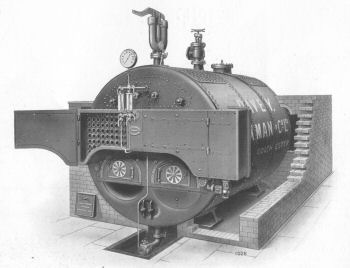
In 1875, only ten years after founding the company, James Paxman introduced his well-known Economic boiler. A highly efficient large horizontal shell boiler, the Economic incorporated smoke-tubes which provided a much larger internal heating surface area than equivalent sizes of the Cornish and Lancashire types of shell boiler then in general use. Andrew Phillips considers the Economic to have been James Paxman's most important contribution to engineering. (3) The Economic, and a later development from it, the Ultranomic, were by far the most important of the wide variety of boilers produced by Paxman in over a hundred years of boilermaking. The Company's reputation as a leading manufacturer of large industrial boilers was built on the success of the Economic and Ultranomic. Both types were made in large numbers and remained in production, with some design modifications over the years, until shell boilermaking came to an end at Colchester in 1967.
A large and well-equipped extension to the Boiler Shop was built in 1894, after which James Paxman claimed to have one of the largest and most complete boiler works in the United Kingdom. (4)
The Economic, Ultranomic and certain other types of Paxman boiler were each built in two forms: one for generating steam and the other for producing hot water. The latter, for perfectly logical reasons, were described by Paxman as 'hot water heaters' rather than boilers.
During the late nineteenth century and the first quarter of the twentieth century a large proportion of Paxman boilers were supplied for use with steam engines, both in the UK and abroad. After the First World War the reciprocating steam engine was rapidly displaced by the oil engine as the prime mover of choice. However, boilers for steam generation remained in strong demand for industrial processes and heating systems in factories and offices. Hot water heaters also continued to sell well for feeding central heating systems and providing hot water supplies in industrial, commercial and institutional premises. Laundries were a growing market for boilers in the years between the First and Second World Wars.
Paxman was a major player in the British shell boiler industry, highly respected by both customers and competitors for the quality of its products. The Company was a founder member of the Association of Shell Boilermakers (ASB), a trade body formed in 1933, to which the great majority of its competitors also belonged. The first Chairman of the Association was Percy Sanders (later Sir Percy Sanders), who at the time was Joint Managing Director of Paxman. The ASB was mainly concerned with the maintenance of prices and operated a pool and quota system for sharing available work among its members. It fixed the artificially high prices of boilers sold by its members and closely controlled the arrangement, thus eliminating any price competition. Even as late as the 1950s, member companies were required to quote customers using prices laid down in the Association's 'red book'. To ensure compliance with the pricing rules, quotations had to be approved by a firm of chartered accountants appointed by the Association, Jones, Crewdson & Youatt of Manchester, before they could be submitted to customers. In 1957 the Restrictive Trade Practices Act 1956 came into operation and, rather than face the heavy cost of defending an agreement which the Association had been advised was vulnerable, the decision was made to discontinue price fixing. (5) Other activities of the Association included cooperation on technical matters such as boiler standards and design. Paxman engineers played their part in this, as well as making important contributions to the work of the British Standards committee responsible for establishing quality standards for shell boilers.
Tony Scott recalled that the pricing of boilers was related to their output. In the late 1940s the selling price was reckoned to be about 10 shillings (decimal equivalent = 50 pence) per lb of steam per hour and he thought that was for the whole steam raising equipment, i.e. boiler and ancillary plant. He guessed that 1939 prices would be about half this. He also suggested that the price increased to 15 shillings (75 pence) during the 1960s but went back to 50 pence in the latter end of the 1970s, at least in the company for which he then worked.
After the Second World War Paxman's boilermaking activities came under the company's Boiler & General Engineering Division (BGED). The BGED was also responsible for manufacturing rotary vacuum filters. In about 1960 the BGED became the Boiler and Industrial Plant (BIP) Division, presumably to reflect the changing nature of its work. During the 1950s the BGED had acquired the specialist equipment and skills to undertake Metal Inert Gas (MIG), Tungsten Inert Gas (TIG) and submerged-arc welding, giving it the capability to weld materials such as aluminium and stainless steel. The Division then expanded its activities to include the fabrication of pressure vessels in mild and stainless steels. Other new work was specialist welding and fabrication of structures for industries such as nuclear power, chemicals, oil refining and papermaking. (6) In 1955 Paxman was the first company in East Anglia to gain approval for welding to Lloyds Class 1 standards. The following year the company became approved for welding stainless steel to the Grade A standards of the UK Atomic Energy Authority.
Although most people now associate Paxman with the manufacture of high-speed diesel engines, it should not be forgotten that boilermaking remained an important part of the company's activities at Standard Works until at least 1967.
Descriptions of most, but not all, of the different types of boiler made by Paxman, together with some history of their development, are given below. Also described is the introduction into the Boiler Shop of new plant and manufacturing technology during the 1950s when Paxman adopted all-welded shell boiler construction in place of the traditional riveted construction. Lastly, there is an account of the events leading up to the cessation of shell boiler manufacture at Colchester in 1967 and the end of boilermaking at Paxman in 1969.
![]() back to Index
back to Index
Vertical Boilers
 As noted above, the earliest boilers produced by Paxman were vertical types. For customers requiring only modest outputs, these types proved very popular and sold in large quantities. They had the advantages of being easy to move about and occupying minimal floor space. Installation was quick, straightforward and cheap as no special foundations or brick setting were needed.
The design of the boiler exhibited by James Paxman at Oxford in 1870 had a relatively complicated internal arrangement. Water tubes descended from the top of the fire-box, down some distance towards the fire, before bending outwards to, and being secured in, the sides of the box. This design was phased out during the early 1890s, having been superseded by a simpler cross-tube arrangement with smoke tubes instead of water tubes. The cross-tube design was better suited for conditions where water quality was poor and competent stokers were unavailable which made it attractive for many export markets.
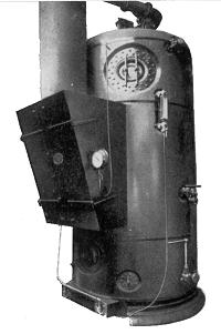
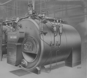
Right: A later type of Paxman vertical boiler as shown in a 1954 catalogue illustration.
A larger, more powerful and better quality version of the basic cross-tube boiler was James Paxman's 'Essex' boiler, launched at the Smithfield Show in the winter of 1885. (7) The Essex became a highly successful product and continued to sell in steady numbers well into the 1930s. Detailed descriptions of the Essex Patent Vertical Boiler and the Improved Cross-Tube Vertical Boiler can be found on the page Early Paxman Vertical Boilers.
Paxman was still offering vertical boilers in the 1950s. The one pictured here, from a 1954 publication, had a normal rating of 2,500 lbs of steam per hour. In a 1959 catalogue its dimensions are given as 6' 6" diameter x 14' 3" high, constructed for a working pressure of 120 psi.
The Economic Boiler
A return-tube, dry-back shell boiler, the Economic was introduced by James Paxman in 1875. Its design was a major advance on the two main types of shell boiler in use at that time, the Cornish and the Lancashire. To aid an appreciation of the advantages of the Economic, and to put them in context, brief descriptions of the Cornish and Lancashire are given here. Readers familiar with these well-known types can skip this section.
The Cornish boiler, the simplest type of shell boiler, was developed by Richard Trevithick. First installed at Dolcoath in 1812, it became popular in Cornwall for raising steam to drive pumping engines in that county's tin mines. Like all shell boilers, the basic structure consisted of a horizontal cylindrical shell, formed from steel plate. Each end of the shell was enclosed by a circular end-plate or tube-plate. Running between the tube plates, inside the shell, was a single large tube, commonly referred to as the 'furnace flue' or just the 'flue'. Alternative names for this are the furnace tube or fire tube. Combustion of the fuel took place on a fire-grate installed in the entrance to the furnace flue, at the front of the boiler. Heat from the combustion gases was transferred from the inner to the outer surface of the furnace flue to heat water inside the boiler. The boiler shell was brickset, that is, set into brickwork. The combustion gases passed first along the furnace flue to the far end of the boiler. They were then channelled towards the front of the boiler, along flues in the brickwork on each side of the shell, so that the sides of the shell acted as additional heating surfaces. Finally, the hot gases passed along a brick flue under the boiler before being discharged up the chimney.
The Lancashire boiler was so named because of its widespread use in Lancashire's cotton mills to raise steam for the engines driving spinning and weaving machinery. Developed from the Cornish boiler by Sir William Fairbairn, it first appeared in 1844. The Lancashire was brickset, like the Cornish, but differed in having two furnace flues, set side by side, each with its own flue system. After passing along the furnace flues to the back of the boiler, the combustion gases travelled through a brick flue under the shell, to the front of the boiler. Finally they passed along brick flues on each side of the boiler, to heat the outer sides of the shell, before escaping up the chimney. By stoking each furnace alternately it was possible to maintain a steady constant draught in both furnaces. The whole arrangement made for a smaller boiler than a Cornish one of equivalent output. A variation of the Lancashire was the Galloway which had water tubes fitted across each furnace flue. This improved heat transfer from the combustion gases when at their hottest to the water and strengthened the flue.
At one time Paxman offered both Cornish and Lancashire boilers, alongside the Economic. The Lancashire boiler remained popular long after more efficient types of boiler became available because of its relative simplicity of construction and operation. Lancashire, and even Cornish, boilers continued to be sold until at least the 1930s.
Key Features of the Economic Boiler
Larger sizes of the Economic had two furnace flues, like the Lancashire, whereas the smaller sizes had only one.
Return-Tube – Double Pass and Treble Pass
The most significant innovation in the Economic was the addition of return-tubes or smoke-tubes between the end-plates, which greatly increased the heating surface area, and hence efficiency, of the boiler. With much improved heat transfer from the combustion gases to the boiler water, the Economic was little more than half the length of a Lancashire of equivalent output. Less floor space was required for installation of a boiler of a given rating, with a consequent reduction in building costs. More importantly, from an operating point of view, the larger heating surface allowed more useful heat to be extracted from each pound of fuel and the boiler had a faster response to increases in load.
An array or 'nest' of small-bore smoke-tubes ran between the tube-plates, submerged in the boiler water, above the furnace flue(s). The number of smoke-tubes could run into hundreds. A 12' diameter x 15' long Economic of the 1950s, for example, had around 300 smoke-tubes.
In early Economics the combustion gases passed first along the furnace flue(s) to a reversal chamber at the back of the boiler. Here they were reversed and then passed or 'returned' through the smoke-tubes to the front of the boiler, before being exhausted up the chimney. Such an arrangement is described as a 'double pass' boiler: the combustion gases passing twice along the length of the boiler, once in each direction, before escaping to atmosphere.
 In time, a 'treble pass' version of the Economic was developed. This had two nests of smoke tubes running between the tube-plates, one nest sitting above the other. As in the double pass type, the first pass of the combustion gases was along the furnace flue(s) to the reversal chamber at the back of the boiler. The second pass was made from the reversal chamber, through the lower nest of smoke-tubes, to the front of the boiler. Entering a smoke box attached to the front of the boiler, the gases were reversed again to make a third pass, through the upper nest of smoke-tubes, to the chimney at the back of the boiler.
Although the treble pass was a little more efficient than the double pass, it has been suggested this was not the main factor influencing a customer's choice between the two. Fuel efficiency was not a big issue at the time. Choice was frequently determined by the desired or available position for the chimney, i.e. at the front or rear of the boiler.
'Dry-Back' Reversal or Combustion Chamber
In the Economic, the combustion gases passed from the furnace flue(s) into a brick-lined reversal chamber at the back of the boiler. The boiler was described as a 'dry-back', distinguishing it from the 'wet-back' type in which the reversal chamber is contained entirely within the boiler and is surrounded by boiler water. The chamber is properly called a 'reversal chamber', being the place where the flow of combustion gases is reversed before they pass to the front of the boiler. However, Paxman described it as the 'combustion chamber' because of its function in promoting full combustion of the gases received from the furnace. In its publicity literature, the Company claimed that a great advantage of the brick-lined chamber was that it became practically red-hot when the boiler was at work, 'thus ensuring the almost perfect combustion of the gases, and reducing the smoke to a minimum'. (8)
Brickset, Semi-Self-Contained and Self-Contained Types
 The Economic was built in brickset, semi-self-contained and self-contained versions.
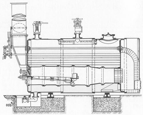
Cutaway illustration of a brickset Paxman Economic boiler.
The brickset type had its combustion chamber built as part of the brickwork setting. It also had flues built into the brickwork along each side of the boiler. The combustion gases passed from the combustion chamber, through the smoke-tubes, to a smoke-box mounted on the front plate of the boiler, and finally returned through the flues in the brickwork to the chimney at the rear.
The self-contained type did away with all the work and expense of a brickwork setting. The combustion chamber was formed by an extension of the boiler's steel shell, the extension being lined with firebrick. The arrangement made for a very compact boiler and this type became increasingly popular in the 20th century.
The semi-self-contained type had a brick-built combustion chamber at the back of the boiler shell, like the brickset type, but not the side flues and other bricksetting. In both the self-contained and semi-self-contained types, the combustion gases, after passing through the smoke-tubes, were discharged via an uptake to the chimney.
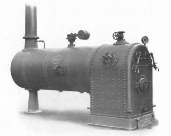
Arrangement of a double pass Paxman Self-Contained Economic Boiler.
Fuels and Draught
The Economic was designed originally to burn solid fuels, typically coal, which remained an important option even up to the 1960s. Other solid fuels included anthracite, coke, wood and, in some overseas installations, bagasse, the waste from sugar cane processing. After World War 2 gas and oil became increasingly popular fuel options, for which the Economic required little adaptation: mainly replacing the fire-grate with gas jets or an oil burner. Important considerations in the use of gaseous and liquid fuels are the shape of the flame and a carefully controlled air supply to ensure full combustion. These can be highly technical matters which lie in the province of the combustion engineer rather than that of the boiler designer.
Draught is a vitally important matter to be considered in the design and operation of any type of boiler. An adequate supply of air is essential for proper combustion of the fuel to take place. Boilers like the Cornish, the Lancashire and the early Economic relied on 'natural draught' to draw sufficient air through the fire-grate for good combustion. The strength of natural draught in such boilers depended on the height of the chimney. Some solid fuel fired Economics in the twentieth century used 'induced draught'. An electric fan was fitted between the smoke-tubes and the chimney to induce or draw the combustion gases and air through the boiler. Gas and oil-fired versions required 'forced draught'. A fan was used to force air into the boiler, in the vicinity of the gas or oil jets, to supply the air necessary for combustion. (Some types of boiler are 'balanced draft', employing a combination of forced and induced draught.)
Boiler Outputs, Sizes and Working Pressures
The output of Paxman steam boilers was measured in pounds of steam (evaporated water) per hour (lbs/hr), from and at 212° F (100° C). The output of hot water heaters was measured in BThUs (British Thermal Units). In practice, output is affected by factors such as the calorific value of the fuel used, the temperature of the feed water, and a boiler's thermal efficiency.
The sizes and outputs of Economic steam boilers offered circa 1916-1919 are given in Appendix A, near the end of this page.
As at early 1954 the Company was offering the Economic in double and treble pass versions, fired by solid, liquid or gaseous fuel, with steam outputs from 1,800 to 21,000 lbs/hr. The smallest was 5' diameter x 13' 6" overall length, the largest 13' 6" diameter x 22' overall length. In Paxman's 1958 boiler catalogue the Economic was offered in double and treble pass forms, each in a range of eighteen standard sizes, with outputs from 2,000 to 25,000 lbs/hr. (9) The dimensions and outputs of these boilers are shown in Appendix B.
The maximum working pressure for any large shell boiler is generally considered to be around 200 to 250 psig. Economic and Ultranomic steam boilers offered by Paxman immediately after World War 2 were built for seven working pressures between 100 and 220 psig. Hot water heater versions of these boilers were built for two standard pressures, 50 and 80 psig.
Long Service Life and a Long Production Life
The Paxman Economic earned a reputation for durability, low cost of maintenance and long life. A magazine article of June 2000 referred to four Paxman Dryback Economic boilers, each rated at 16,000 lbs/hour, which had been installed at Newcastle General Hospital in 1962. Fired by pulverised coal, they were the last of their type in a hospital environment and had just been replaced. The writer of the article commented that despite their age, the boilers had good combustion efficiency. The installation had no less than twelve electric motors to drive ancillary equipment, comprising vibrator, elevator, conveyor, feed table, attritor (mill), force draught (2), induced fan, dust worm, dust cyclone, dust conveyor and rotary screw. It is a testament to the quality of the boilers' design and manufacture that they gave nearly forty years of good service.
The Economic remained in production for a remarkably long period: over ninety years. It was still in demand and being made up to the time shell boiler manufacture ceased at Colchester in 1967. Naturally various improvements and new manufacturing methods were introduced over the years but in essentials the 1960s Economic was little different from its 19th century predecessors.
![]() back to Index
back to Index
Locomotive-Type Boilers
 Paxman built locomotive-type boilers from at least the early 1880s up to the early 1930s. They were produced in large numbers, particularly during the last decade of the 19th century and the early years of the 20th century. The numbers built were sufficiently great to justify the Great Eastern Railway Company designing and making special railway trucks on which to transport them to Paxman's customers.
Right: Raised fire-box type of Paxman locomotive boiler.
Installation of this type of boiler was simple and relatively cheap. No special foundations or brickwork setting were required, nor a brick chimney. Once in place the boiler could quickly be set to work. Other advantages were that it contained a large heating surface and grate area within a comparatively small space and that the grate could be arranged to burn any kind of solid fuel. The boiler was also relatively light in weight which made it attractive to export markets where the logistics and cost of delivery were important considerations.
Paxman manufactured locomotive boilers in a wide range of sizes from 2 hp upwards, suitable for working pressures of 120 psi and upwards. There were two designs, the raised fire-box type and the flush fire-box type, the top of the fire-box of the former being raised above the level of the top of the boiler barrel. The largest size of locomotive boiler advertised in an early 20th century catalogue had a 6' diameter barrel, a total heating area of 1,750 square feet and was designed for a working pressure of 220 psi. (10) Dimensions and outputs of raised fire-box types are given in Appendix C.
All-Steel Sectional Boilers
 Paxman started making sectional hot water boilers at least as early as 1926. (11), At this stage they were presumably of cast-iron construction. All-Steel Sectional Boilers were introduced in the early 1930s. Designed for central heating and hot water supply services, they were efficient boilers which sold in large numbers. Paxman was still advertising them in 1961, some thirty years after they first appeared. Typical customers were schools, offices and hotels.
A key feature highlighted in publicity literature was their construction from mild steel plates with the advantage that, unlike cast iron boilers, they were not liable to fracture. They could also be expected to have a longer life. As their name implies, the boilers were made up of a number of sections. Each section consisted of an inner and outer element of inverted 'U' shape, containing boiler water, the spaces between the elements forming the flues.
The individual sections were fabricated from mild steel plates which were assembled and clamped in a jig before being welded up. The latter operation was carried out by electric arc welding, a process which Paxman had started to use only shortly before introducing this type of boiler. Sections could be delivered to customers as individual units, before being assembled on site as a complete boiler. This feature greatly facilitated handling for transport and installation in boilerhouses with restricted access.
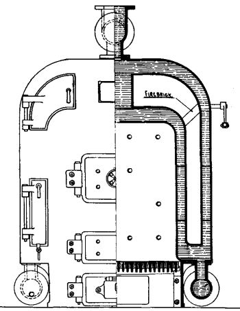
Left: Sectional view of All-Steel Sectional Boiler
An All-Steel Sectional Boilers catalogue of the 1930s (12) gives details of three Series: 0, 1 and 2. Each Series was offered in three types: one for central heating by hot water, one for central heating by low pressure steam, and one for hot water supply. Each type in each Series was offered in six different sizes. The smallest consisted of only two sections, a front and a rear. In the original pre-war versions, these front and rear sections were provided with hollow back plates, forming water walls. Larger sizes of boiler were built with up to five intermediate sections sandwiched between the front and rear sections, the number of intermediate sections depending on the output required. The dimensions and outputs of each Series are shown in the following table:
| Paxman All Steel Sectional Boilers (pre-World War 2) | ||||
|---|---|---|---|---|
| Length | Width | Height (excl header) | Output BThUs/hour. | |
| Series 0 | 19½" to 59½" | 39" | 50½" | 150,000 - 525,000 |
| Series 1 | 30" to 105" | 45" | 64" | 430,000 - 1,430,000 |
| Series 2 (as originally printed in catalogue) | ||||
| 36" to 126" | 54" | 70" | 810,000 - 2,760,000 | |
| Series 2 (as shown on pasted-in amendment sheets) | ||||
| 41" to 143½" | 66" | 82" | 810,000 - 2,760,000 | |
 From catalogues and discussions with ex-Paxman boiler staff it appears that from the late 1940s sectional boilers were made only in one width and height. This may have been the Series 1A, with dimensions close to those of the pre-war Series 1. Perhaps the 1958 Paxman Boilers catalogue description of All-Steel Sectional Boilers is referring to the Series 1A when it talks of "Improvements in the design, methods of production and developments introduced in this catalogue …". (13) As advertised in the 1958 catalogue and a January 1960 information sheet (14) this boiler was offered in six sizes. The smallest had three sections: a front, a rear and one intermediate. The largest consisted of eight sections, six of these being intermediates. The front and rear sections were now lined with firebrick instead of having hollow back plates containing boiler water and each intermediate had three water tubes connecting the inner and outer element. A treble pass design, outputs were from 600,000 to 1,620,000 BThUs/hour. Lengths ranged from 56" to 131.5/8", the width was 45" (excluding return headers) and the height 62½" (excluding flow header). Although suitable for solid fuel, oil or gas firing, as hitherto, sectional boilers were by this time predominantly oil fired.
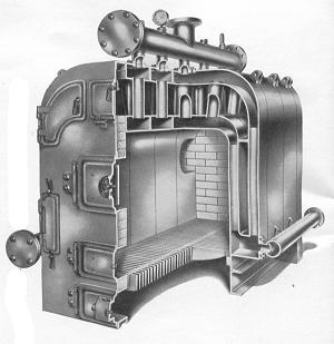
Right: Cutaway illustration of post-war All-Steel Sectional Boiler
A later publicity leaflet, dated February 1961, shows the sectional boiler then being available in eight sizes, having between three and ten sections. The largest had a rating of 2,000,000 BThUs/hour.
![]() back to Index
back to Index
The Ultranomic Boiler
The Ultranomic was a development of the Economic and shared many of its features. It was second only to the Economic in its importance to Paxman's boiler business, selling in large numbers right up to the time shell boiler manufacture ceased at Colchester in 1967. Introduced in 1936, it was designed by Lufkin Hazell who joined the Company circa 1886 and rose to become Chief Boiler Engineer. Robert Lufkin Keable Hazell had served Paxman for well over sixty years by the time of his retirement in December 1947. He died at Frinton in December 1950 at the age of 83. (15)
The introduction of the Ultranomic was reported in the October 23rd, 1936 issue of Engineering, together with a technical description of the new boiler, covered at the time by a provisional patent. The article included a photograph of three 8' 6" diameter x 9' 6" long Ultranomics being erected at Kent and Canterbury Hospital.
The Ultranomic differed from the Economic in that all versions had only one furnace tube, positioned to the left or right of the centre line of the boiler, and placed higher in the shell. The smoke tubes were arranged on the opposite side to the furnace tube, alongside it rather than above, as shown in the diagram below.
End and side view diagrams showing layout of a treble pass Ultranomic.
The Ultranomic, like the Economic, was built in double pass and treble pass versions. In the double pass type the combustion gases first passed along the furnace tube to the combustion chamber at the rear of the boiler. Here they were reversed before making a second pass through the nest of smoke tubes to the front of the boiler, where they were exhausted up the chimney. The treble pass type had two nests of smoke tubes, both positioned to one side of the furnace tube, one nest sitting above the other. The combustion gases passed along the furnace tube to the combustion chamber at the rear of the boiler and, after being reversed, made a second pass through the lower nest of smoke tubes to the front of the boiler. Here they entered a smoke box, attached to the front of the boiler, where they were reversed again, to make a third pass through the upper nest of tubes, before being exhausted up the chimney at the rear of the boiler.
 The general arrangement of the Ultranomic was claimed to have a number of advantages over that of the Economic. By placing the furnace crown higher up in the boiler, steam was produced more quickly and efficiently. Having the crown, where the greatest amount of heat is liberated, near the surface of the water facilitated the free escape of steam bubbles. The lower smoke tubes, close to the bottom of the boiler, promoted a natural and positive circulation of the whole body of boiler water, eliminating any 'dead' spots. The layout offered better access for internal maintenance. There was room for a full size manhole at the front of the boiler, in addition to the one on top, and more working space around the furnace tube.
Coal-fired treble pass Ultranomic installed at the Art Metal Construction Co, Wembley, in 1947.
Tony Scott, a former senior member of Paxman's Boiler Drawing Office, has questioned whether the advantages of the Ultranomic over the Economic were as great as was claimed. The issue of how much more quickly the Ultranomic could raise steam was, he thought, perhaps rather academic. In normal practice both types would probably be brought up to steam relatively slowly. Once there, the boilers would not usually go completely cold until the annual shutdown when repairs and maintenance were carried out.
As at early 1954 the company was offering double pass Ultranomics with outputs ranging from 1,800 to 11,085 lbs/hour, and treble pass types with outputs from 1,800 to 11,500 lbs/hr. The maximum ratings quoted here were for types fitted with mechanical stokers; for hand fired types they were somewhat lower. The maximum output of the largest Ultranomic was little more than half that of the largest Economic then made. The smallest Ultranomic at this time was 6' diameter x 10' 6" overall length, the largest 10' diameter x 21' overall length. Dimensions and outputs of Ultranomics offered in Paxman's 1958 catalogue are shown in Appendix D.
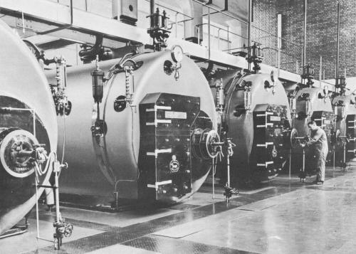
Installation of 5 treble pass Ultranomic boilers at the Bristol Aeroplane Company, Filton.
The Ultranomic, like the Economic, was capable of an exceptionally long life. A 1939 coal fired Ultranomic remained in use at Harvest Mill, Darwen, Lancashire, until being decommissioned on 30th January 2005 after 65 years service. It is possible the boiler may originally have been installed in John Lewis's Oxford Street, London store and later moved to Harvest Mill.
Important later forms of the Ultranomic were the 'packaged' type, introduced circa 1958, and Super Ultranomic which appeared circa 1962. Both are described later on this page.
![]() back to Index
back to Index
Boiler Production During World War 2
Boilermaking continued to be an important element of Paxman's production throughout the years of the Second World War. During the war the Boiler Works were expanded considerably to deal with big commitments for marine and industrial boilers. One government contract was for twelve marine-type wet-back boilers, each of 9' 0" diameter x 9' 6" long, for installation in steam tugs. In a small booklet published in June 1945 (16), recording the Company's achievements in diesel engine production during the war, is the following list of the types of boilers being made at Standard Ironworks in mid-1945:
Brickset and Semi-Self-Contained Type Economic Boilers, a range of 21 sizes from 5' 0" diameter by 8' 0" long to 12' 6" diameter by 16' 0" long, built for 7 working pressures between 100 and 220 psi.
Self-Contained (Two-Pass Type) Economic Boilers, a range of 21 sizes from 5' 3" diameter by 8' 0" O.T.P. 10' 3" overall to 12' 6" diameter by 16' 0" O.T.P. 19' 9" overall. They are built for 7 working pressures between 100 and 220 psi.
Self-Contained (Treble-Pass Type) Economic Boilers, for a range of 18 sizes from 5' 3" diameter by 7' 3" overall length to 12' 0" diameter by 14' 3" overall. They are built for 7 working pressures between 100 and 220 psi.
Self-Contained (Treble-Pass Type) Economic Boilers for Hot Water, a range of 16 sizes from 4' 9" diameter by 7' 3" overall length to 9' 9" by 13' 0" overall. They are built for two pressures, 50 and 80 psi.
Double-Pass "Ultranomic" Type Steam Boilers, a range of 14 sizes from 5' 9" diameter by 11' 9" overall length to 10' 0" diameter by 19' 3" overall. They are built for 7 working pressures between 100 and 220 psi
Treble-Pass "Ultranomic" Type Steam Boilers, a range of 15 sizes from 5' 9" diameter by 8' 3" overall length to 11' 0" diameter by 13' 9" overall. They are built for 7 working pressures between 100 and 220 psi.
Treble-Pass "Ultranomic" Hot Water Boilers, a range of 16 sizes from 4' 9" diameter by 7' 3" overall to 9' 9" diameter by 13' 0" overall. They are built for two standard pressures, 50 and 80 psi.
The Aquanomic
A small booklet about the Company, dated March 1948, contains the following reference to this boiler: "The latest addition to the Paxman range, the Aquanomic Boiler has been specially designed to provide a boiler for heating by low pressure hot water, efficient and reliable in operation, of substantial construction at low production cost, and at the same time easy to erect, particularly in difficult locations. … Constructed as a complete unit including all brickwork lining, the boiler can be lifted by means of four lugs into its required position. This accomplished, it is only necessary for two water connections to be made, when the boiler is ready for work." (17)
The booklet shows a picture of an Aquanomic arranged for oil firing. It has a cylindrical boiler, with two nests of smoke tubes, the whole being mounted on top of a rectangular base which contains the combustion chamber. I have come across no other reference to the Aquanomic and think that few, if any, can have been made.
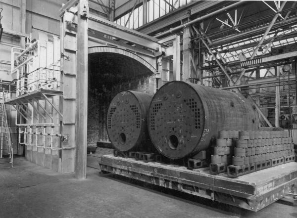
Paxman's Boiler Division in the 1950s
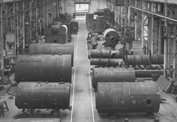
The above picture is of the Boiler Shop in the latter half of the 1950s. The five shell boilers in the foreground are all of riveted construction. Behind the third boiler on the left is a water tube boiler under construction. To the right of this is a drum for a rotary vacuum filter. In front of the filter drum are flues for shell boilers.
The 1950s was a decade of great activity in the Company's boiler business. It was marked by a good deal of innovation and development in both boiler design and manufacturing methods. The impression gained from talking to men who worked in the boiler division at the time is of a confident, prospering business which explored new avenues with energy and enthusiasm.
Those who worked in the Boiler Drawing Office at the time recall the strong family atmosphere and camaraderie which then existed in the boiler business and, indeed, in other parts of Paxman. Colleagues enjoyed a robust sense of humour and a good sense of fun. This was against a background of relatively hard times as Britain continued to struggle with post-war rationing and shortages. Furthermore, pay at Paxman was never generous. Friendships formed then have endured well into the twenty first century. As at 2011, former members of the Boiler Drawing Office still meet up regularly to share a meal and a drink together, to catch up on each other's news and to talk about old times.
During the 1950s George Blackwood was Paxman's Chief Boiler Engineer. He probably succeeded to this appointment when Lufkin Hazell retired in December 1947. He is thought to have joined Paxman in 1946, having previously worked for the Greater London Council (GLC). George Blackwood was a Scot, a careful design man, who had a good knowledge and understanding of boilers. He is believed to have retired in the autumn of 1962. Although he has been described as careful and conservative, it was during his time that Paxman introduced high velocity versions of the Economic and Ultranomic, moved from riveted to all-welded construction of its shell boilers, obtained a licence to manufacture water-tube boilers and started to build 'packaged' boilers. These changes are described in subsequent sections of this page.
Other personalities in the Boiler Division in the 1950s were Percy Turner and Jack (Geordie) Davison. Percy Turner was Chief Draughtsman and had been with the Company since at least the time of the First World War. Jack Davison was Assistant Chief Draughtsman and took over from Percy Turner when the latter retired in 1958. However, he did not remain in this position for long. Within about three years he moved over to the Contracts and Sales side of the boiler business, after which Fred Appleton, who worked in the filtration side of the business, was appointed Chief Draughtsman of the Boiler & General Engineering Division.
Percy Turner retired in late June 1958. In the late 1950s and early 1960s various other members of 'the old guard' also retired. The arrival in 1957 of Commander Peter F Hoddinott, who had previously been an Engineering Officer in the Royal Navy (18), brought a wind of change. Tony Scott, a former senior member of the Boiler Drawing Office, has described Peter Hoddinott as 'a breath of fresh air', a man who "adopted a scientific approach to doing things". He applied scientific principles to boilermaking which previously in Paxman had been practiced more as an art. Peter Hoddinott may have been appointed initially as a Design Engineer but certainly by March 1964 he was Manager - Boiler Sub-Division, and by 1968 Chief Engineer, Boilers. He was innovative and came up with many new ideas. Frequently these were met with scepticism, if not dismissal, by some members of his staff. Tony Scott thought that possibly a number of Peter Hoddinott's ideas were before their time and ambitious, bearing in mind the resources then available in Paxman's Boiler Division.
Bob Bensly was Works Manager of the Boiler Works and Foundry in the late 1950s and up to December 1960. He is remembered as being a very able manager. Among other things he considered presentation to be important and expected a professional finish to boilers, with attention to details such as neat electrical wiring and pipework on packaged boilers. Bob Bensly had joined the Company as a Student Apprentice in 1939 or 1940 and subsequently worked with Geoffrey Bone in the Experimental Department before moving into manufacturing management roles. From 1st January 1961 he became responsible for the Works Management function across the whole Standard Works site. (19) Later he was appointed Works Director and then, in 1967, Managing Director.
![]() back to Index
back to Index
High Velocity and Medium Velocity Boilers
A Paxman boiler catalogue of c.1953 announced that "A recent introduction is the High Velocity design", and that this design was available in both the Economic and Ultranomic ranges. (20) The Company's 1958 boiler catalogue explained that 'In high velocity boilers, the speed of the combustion gases is accelerated through the boiler, leading to higher efficiency and a reduction in fuel consumption.' This resulted from higher rates of heat transfer. The 1958 catalogue also contained a note that 'On account of the higher resistance to gas flow in the High Velocity treble pass boiler it is essential in all cases to include forced or induced draught arrangements.' By this time both the double and treble pass versions of the Economic and Ultranomic are stated to be available in medium and high velocity designs. (21)
The high velocity design allowed for a more compact and efficient boiler. Another benefit of the high velocity design was a reduced need for tube cleaning. The faster rate at which the combustion gases passed through the smoke tubes allowed less opportunity for any solid particles carried in the gases to settle inside the tubes.
Medium velocity boilers were intended primarily for coal firing and had 3" diameter smoke tubes throughout. High Velocity boilers were designed principally for oil firing and eventually it became the practice always to offer a high velocity boiler for oil-fired installations. The double-pass types of these were built with 2" diameter tubes throughout. In high velocity treble pass boilers the second pass was through 3" tubes and the third pass through 2" tubes.
From Riveted to All-Welded Shell Boiler Construction
Paxman produced its first all-welded shell boiler in 1955. Up to that time, in line with general practice in British boilermaking, all its shell boilers were of riveted construction. The operations involved in riveted construction were time-consuming and labour intensive. Every rivet hole had to be marked out on the various sheets of steel plate and drilled, before each pre-heated rivet could be inserted and closed. At Paxman rivets were generally closed using one of two hydraulic riveters. The larger one stood in the riveting tower where it was used for riveting work on both shells and furnace tubes. These were lifted into a vertical position and rotated between the jaws of the machine which closed each rivet with a pressure of 100 tons. A smaller portable riveter was used for riveting furnace tubes to end-plates. Where hydraulic riveting was impractical, hand riveting was used. For this, one man, the holder-up, held the rivet head hard against the plate while another closed the other end with a pneumatic riveting gun. Riveting provided the mechanical strength for a joint but did not completely seal it so the next operation was caulking. A pneumatic percussive hand tool was used to peen around the edge of each rivet head, along the joints between the end-plates and the shell, and along the edges of butt-straps which overlapped the longitudinal seams of the shell. Both hand riveting and caulking were very noisy operations, the noise of the high speed hammering being amplified by the large hollow steel cylinders on which the work was done. The initial caulking was not always entirely successful so remedial work was frequently required, either when leaks became apparent during subsequent hydraulic testing or when a boiler was first steamed after installation. The various stages of construction of a riveted boiler were described in 'The Building of a Boiler', published in a 1952 issue of Paxmans World. The text of that article is reproduced in Appendix E.
Paxman was one of the first British boilermaking concerns to move to all-welded construction of shell boilers. Welding was much more efficient than riveting, offering substantial savings in cost, manpower, and build time. A further advantage was reliability, eliminating the problem of leaks around rivets and the consequent need for remedial work.
Paxman had used electric-arc welding in boilermaking since the early 1930s, but only for the manufacture of its sectional boilers. These were small boilers operating under relatively low pressures. Large steam shell boilers, operating under pressures of up to 200-250 psi, were an entirely different proposition. The first type of welding used by Paxman on shell boilers was forge welding, a very old technology. It was used only on the longitudinal joints of individual sections of furnace tubes. The longitudinal seam of each section was brought to welding heat by a coal gas burner and the two edges were joined together by applying pressure with a top and bottom roll. Any lack of fusion or any thinning out was made good with oxy-acetylene welding, after which the sections were joined at the expansion joints by riveting. From about 1952 onwards electric-arc welding was used for the seams of furnace tubes. At first, this arc welding was done by hand, as shown in a photograph in a Paxman boiler catalogue of c.1953. (20)
In preparation for the introduction of all-welded shell boilers in 1955, Paxman installed two fully automatic submerged-arc welding machines. A large one carried out longitudinal and circumferential welds on the boiler shells or outer wrappers. A smaller one was used for similar welds on furnace tubes. Using the submerged-arc method, the welding is shielded by a 'blanket' of granular fusible material laid on the work. The bare electrode is power fed into this blanket so that the arc and molten metal are immersed in flux at all times, thus preventing exposure to air and weld defects caused by oxidation. Being fully automatic, the machines eliminated human error. They could produce high quality welds with deep penetration and minimum distortion to meet Class 1 standards for pressure vessels. Shortly after, probably in 1956, the company invested in a third fully automatic submerged-arc machine for welding end-plates onto boiler shells. Designed by Jim Edwards, this revolving column version was built by the Surrey Tool Development Company.
Jim Edwards was Paxman's acknowledged expert on welding; highly respected by colleagues for his abilities, experience and knowledge in this field. He commenced his apprenticeship with the Company in December 1933 and very quickly displayed a strong natural aptitude for welding. He came up with solutions to a number of welding problems which the business needed to resolve. Among these were the introduction in the early 1950s of techniques for welding aluminium engine crankcases and larger aluminium structures. Jim Edwards was a strong believer in eliminating or reducing the human element wherever possible by using automatic machines and jigs. In September 1955 he was appointed Paxman's Welding Methods Engineer and later Chief Methods Engineer, a position he held up to his retirement in January 1981. (22) With the welding advances pioneered by him, the Company acquired the facilities and skills which enabled it to branch out into the fabrication of specialist pressure vessels.
Paxman's decision to adopt all-welded construction of shell boilers necessitated investment in a large stress relieving furnace. The high temperatures created by arc-welding, and the relatively rapid subsequent cooling, set up stresses in welds and surrounding areas of plate. With a boiler, or other similar pressure vessel, it is essential to relieve the stresses by gradually heating up the vessel in a furnace, soaking it at 600° - 650° C for a time, and then allowing it to cool at a carefully controlled rate. Paxman's Colchester Newsletter No 10, of December 1955, reported that the Company "… have installed a further heat treatment (stress relieving/annealing) furnace with internal measurements 28' long x 10' 6" wide x 10' 4½" high … bogie capable of taking a cylindrical vessel of 10' diameter x 28' long, weighing up to 45 tons." Until 1960/61 boilers of larger than 10' diameter could only be built using riveted construction (the 1958 catalogue offered Economic boilers up to 14' diameter).
In about 1959 Paxman built a large riveted boiler for Bradwell Power Station in Essex, which was then under construction. The boiler leaked at some of the rivets. The Managing Director, Geoffrey Bone, was so embarrassed by the incident that he insisted on a move to all-welded construction for all boilers within six months or so. This could only be achieved by investing in a larger stress relieving furnace. Faced with an outside quotation of around £45,000 for a suitably sized furnace, Jim Edwards's boss, Bob Bensly, asked "Could we make one?". Jim drew up plans for a new furnace and a cost estimate of around £12,000 which included £1,000 for contingencies. These received senior management approval and Jim was made responsible for procuring the necessary materials and managing the construction. Perhaps to his surprise, every part of the project went like clockwork. (21) The new furnace was 15' wide x 14' 9" high x 20' long and could accommodate boilers of up to 14' diameter. It was commissioned in 1960 or 1961, after which no more riveted boilers were built at Paxman.
The larger stress-relieving furnace erected in 1960 or 1961, with its loaded bogie.
![]() back to Index
back to Index
Water Tube Boilers
In most of the boilers described previously on this page, the combustion gases pass along the insides of furnace and smoke-tubes. Heat from the gases is conducted from the inner to the outer surfaces of the tubes, to heat the boiler water in which they are submerged. A water tube boiler is fundamentally different. The combustion gases pass around the outer surfaces of 'water tubes'. Heat is conducted from the outer to the inner surfaces of the tubes, to heat boiler water contained within the tubes.
One important feature of water tube boilers is their ability to operate at higher pressures than other types. Shell boilers, for example, have a maximum safe working pressure of about 200 to 250 psig, for technical reasons relating to their construction. Other advantages of water tube boilers are their rapid steaming to full output from cold and quick response to load fluctuations.
As far back as 1889 James Paxman embarked on a determined attempt to construct a water tube boiler. A good deal of experimental work was carried out and two patents were registered. A prototype was built and exhibited at the 1892 Crystal Palace Electric Light Exhibition. Extensive tests were conducted during March 1892 but James Paxman remained unable to make his water tube boiler perform as efficiently as his Economic. Sixteen water tube boilers were sold over the next three years, after which efforts to promote them effectively ceased. A further attempt to develop a water tube boiler was made at the turn of the century. (23) There has been a suggestion that during the late 1940s or early 1950s the Company looked again at designing a water tube boiler. If that is so, nothing appears to have come of it.
In 1954 or 1955 George Blackwood, then Paxman's Chief Boiler Engineer, visited Erie City Iron Works in the USA to negotiate a licence for Paxman to manufacture their VL water tube boiler. He returned with an agreement allowing Paxman to build and market both Erie City's VL and its smaller K-Type (Keystone) water tube boiler. Tony Scott, who worked in the Boiler Drawing Office at the time, has commented that although Paxman went to Erie City primarily to get a licence to build the VL, the licence to make the K-Type was more or less thrown in with that for the VL. A fortuitous outcome as Paxman sold considerably more K-Type than VL boilers. The Company's Colchester Newsletter No 9, of August 1955, announced: "We have acquired from Erie City Ironworks, Erie City, Pennsylvania, USA, the licence to manufacture and sell their well-known "Keystone" and "VL" water tube boilers".
The first K-Type built by Paxman, a size 250K, was completed in late 1955. The Company's Colchester Newsletter No 10, of December 1955, reported: "We have just completed a new packaged "K" Type Water Tube boiler, … . The whole of the work in the manufacture of this boiler has been carried out in our own Works. … This boiler is installed in our Britannia Works where it is to be subjected to exhaustive tests and research and will be available for inspection in operation by clients." This, or another K-Type, was shown at a heating and ventilating equipment exhibition in spring 1956. A photograph showing water tube boilers in build at the Colchester Works appeared in the July/September 1956 issue of British Machine Tool Engineering.
The Company built a reasonable number of K-Types but very few VLs. Water tube boilers are particularly suitable for high pressure applications such as driving steam turbines. Unlike the USA, which had large numbers of small local electricity generating plants, there was a relatively limited market in the UK for high pressure boilers with the outputs of the K-Type and VL.
Production of water tube boilers ceased at Colchester at about the same time as shell boilermaking finished in 1967.
The K-Type, KP and WTK Water Tube Boilers
The K-Type or Keystone, introduced by Erie City in 1949, was derived from the VL as a treble pass, balanced draught boiler.
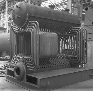 The general layout of the K-Type can be seen in the photograph here of one under construction at Paxman's Works. Running along the centre line of the boiler are two welded steel drums: a water drum at the bottom and a larger steam-collecting and water drum at the top. The two drums are connected by a large number of water tubes which provide the main heating surface and around which the combustion gases flow. The gases flow first from the front to the rear of the boiler, are reversed and pass to the front of the boiler. Here they are reversed again to pass to the rear of the boiler where they are exhausted by an induced-draught fan to the chimney and thence to atmosphere. The boiler was enclosed by fire tile and high-temperature insulation blocks; the whole being contained in a substantial steel casing constructed of flanged panels bolted together.
The K-Type was designed to be fired by a fully automatic oil burner which incorporated a forced-draught fan. Paxman generally fitted Hamworthy burners and controls to these boilers. Alternatively, the K-Type could be arranged for firing with town gas or fitted with a combination gas/oil burner.
All except the largest K-Types were built as 'packaged' boilers; the first 'packaged' boilers produced by Paxman. The 'packaged' concept was soon to have a major influence on Paxman's own boiler designs as we will see later. In the case of the K-Type, the concept involved the boiler with its mountings, its oil burner, induced-draught fan, feed pump and short steel chimney all being mounted on a fabricated steel base. The result was a compact and readily transportable unit. Factory assembly was less costly than field erection and such boilers could be, and were, fully steam-tested at the Works before despatch. Only an ordinary concrete slab was required to support the base. Once delivered to the customer's site it was only necessary to make fuel, water and electrical connections before the boiler could be set to work.
In 1958 and 1961 Paxman brochures, the K-Type was offered in a range of fourteen sizes. (24) The ten smaller sizes were fully packaged, with outputs from 2,500 to 17,000 lbs per hour from and at 212° F. The four larger sizes, having outputs from 20,000 to 33,000 lbs/hr, were supplied as non-packaged or semi-packaged for ease of transport. The K-Type was offered in two pressure ranges: (i) up to 200 psig, and (ii) 200 to 400 psig. Details of the different sizes and their outputs are given in Appendix F.
Sales of Paxman K-Type boilers included two for the Oilwell Engineering Co Ltd, Cheadle Heath, Stockport - 250K size, 8,500 lbs/hr output; three for the Central Electricity Generating Board's Littlebrook Power Station, Dartford, Kent - 300K size for high pressure hot water duty, 9,700,000 BThUs/hr, at an operating pressure of 310 psi; one for Fisons Ltd (fertiliser manufacture), Ipswich; (25) three for J & P Coates Ltd for plants in Colombia, Chile and Peru; two for Abbotts Laboratories (pharmaceuticals), Sheerness, Isle of Sheppey - 500K size, 17,000 lbs/hr; one for Clifton Laundry, Bristol.
Paxman's 1961 Water Tube Boilers brochure offered the K boiler in both its original balanced draught form and as a 'pressurized' design. (26) The latter was subsequently designated the KP. In the 1964 brochure only the KP is offered, not the earlier K-Type. (27) Like the K-Type, the KP was a fully packaged factory-built boiler suitable for oil or gas firing. Although bearing many similarities to the K-Type in construction and appearance, the KP was a 'pressurized', not a balanced draught, design; hence the KP (Keystone Pressurised) designation. It retained a forced-draught fan incorporated in the burner but had no induced-draught fan. Another difference was that the KP was a double pass, not a treble pass, type. The combustion gases made their first pass to the rear of the boiler and then returned to the front through the convection zone, before being exhausted through outlet ports situated either side of the front end of the steam drum.
The KP was designed for operating pressures from 200 to 800 psig, up to twice the maximum operating pressure of the K-Type. It was offered in sizes with outputs from 12,000 to 44,000 lbs/hr. Sales of KP boilers included two for Imperial Chemical Industries Ltd, Port Clarence, North Tees - 400KP size, 13,500 lbs/hr; one for the Nestle Co, Hayes, Middlesex - KP44 size, 44,000 lbs.hr output, 520 psig; two for Laporte Industries Ltd (Laporte Titanium), Stallinborough, Lincs, ordered in 1966 - KP40 size, 40,000 lbs/hr, operating pressure of 650 psi (28); one for West Midlands Gas Board, Birmingham - KP44 size, 39,000 lbs/hr, 550 psig.
 The 1964 Water Tube Boilers brochure offered the WTK boiler to customers needing higher outputs than those available from the KP. Developed from the KP, it was described in the brochure as "a new and advanced design which has been introduced in order to make it possible to offer larger outputs from a factory built packaged water tube unit of overall dimensions suitable for transporting on British roads". With outputs from 50,000 to 100,000 lbs/hr, WTK boilers could be supplied as packaged factory-built units for duties up to 80,000 lbs/hr. Larger sizes were erected on site. Like the KP, it could operate at steam pressures up to 800 psig.
Right: Outline layout of the WTK boiler.
Unlike more conventional designs, which were fitted with a small water drum and a single large steam drum, the WTK was constructed with three longitudinal drums of equal diameter: a water drum in the lower part of the boiler and, at the top, a steam generating drum and a steam offtake drum. A convection zone in the boiler was separated from the combustion area by a wall of tubes arranged between the water drum and the steam generating drum. The WTK was equipped with twin fully automatic oil burners but could be adapted for gas firing.
As far as Tony Scott can recall, Paxman never actually made a WTK boiler.
The VL (Vertical tubes with Longitudinal drums) Water Tube Boiler
The VL was a single pass design, the fuel being burned at the front of the boiler and the combustion gases exhausted at the rear, without any reversal. It was suitable for oil or gas firing or for coal firing using a mechanical stoker with semi or fully automatic control. By 1961 the VL was also available for pulverised fuel firing. (29)
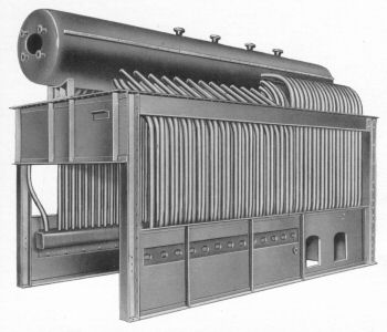 The VL had a steam drum at the top, extending the full length of the boiler. This was designed to provide ample water storage space and a large surface for the release of steam. At the bottom, to the rear of the boiler, was a shorter water drum. In the front part of the boiler, water tubes went up from side headers at the bottom and arched into the steam drum at the top. At the rear of the combustion chamber was a nest of water tubes which connected the water drum to the steam drum. Baffles were fitted in the convection zone to direct the flow of the combustion gases and maximise the heat absorbed by the water tubes. The whole was enclosed within a fabricated steel casing to make a self-contained unit.
Right: Illustration of the arrangement of the VL, without its insulation, steel casing, burner and fittings.
Except for the largest sizes and those made for pulverised fuel firing, VL boilers were supplied as factory-assembled units. For these, the main work required on site prior to installation was the laying of a refractory brick floor. To prevent the risk of heat transfer through this floor damaging the foundation, drainpipes were incorporated in the base to provide an air flow.
In 1956 Paxman was offering the VL in seven sizes, with outputs from 6,600 to 20,000 lbs/hr, operating at steam pressures up to 400 psig. (30) In the 1958 Paxman Boilers catalogue one larger size has been added to the range and it is stated "Boilers up to 23,000 lbs/hr … are erected complete in our works before despatch." (31) Outputs and dimensions of the range, as published in this catalogue, are reproduced in Appendix G. By 1961 there were nine oil or gas fired VLs in the range (seven sizes for solid fuel firing), the largest having an output of 26,500 lbs/hr, and the maximum operating pressure had been increased to 600 psig. The VL was then available for pulverised fuel firing, for duties between 20,000 and 30,000 lbs/hr. (32) By 1964 the VL was available for duties up to 30,000 lbs/hr and those offered for pulverised fuel firing had outputs from 20,000 and 100,000 lbs/hour. (33)
Two 20,000 lbs/hr VL boilers were supplied to Kraft Foods Ltd, Kirby Trading Estate, Liverpool. (34) Another VL was installed at Dorman, Long Ltd, Middlesborough. (35) Tony Scott thinks that Paxman built only one VL for firing by pulverised fuel. This was a large boiler, having an output of 35,000 lbs/hr and an operating pressure of 400 psi, for the chemical works of Hickson & Welch at Castleford, West Yorkshire. Roy Beardwell, who worked in the Sales Office, had to prepare the quotation for this job. He did not find the task easy as Paxman had never previously supplied a VL of this type, for which all the erection work would have to be carried out on site rather than in the factory. Roy calculated that the quotation should be in the region of £30,000. He put this to his manager, Peter Hoddinott, who told him to quote at £10,000. Roy questioned the very low figure but Mr Hoddinott was in no mood to discuss the matter and insisted that the job be quoted at £10,000. Roy prepared a revised quotation at this price but, unwilling to put his own signature to it, presented it to Mr Hoddinott saying that as he was the one who had come up with the figure he should sign it off. Mr Hoddinott did sign it off but after that never spoke to Roy again. The boiler was erected during the summer of 1961 and Roy's father, Bill Beardwell, one of Paxman's most experienced boilermakers, was in charge of the work on site. At one stage during erection, Bill told his son that he had already spent more than twice the sum of the quotation on the job!
![]() back to Index
back to Index
Packaged Shell Boilers
The concept of the packaged boiler, a boiler together with all its ancillary equipment mounted on a baseplate, originated in the USA during the late 1940s or early 1950s. Its attractions to both boiler manufacturers and customers in the geographically widespread American market can be readily appreciated. The boiler with its ancillaries was supplied as one complete factory-assembled unit, tested before despatch and easily transportable, even to distant customers. On arrival at the customer's premises, installation of the boiler was quick and straightforward, incurring very little additional expense.
Paxman gained first hand experience of American packaged boiler practice when it started to build Erie City's K Type water tube boilers under licence, as described earlier on this page. This may have been one factor influencing the Company's decision to develop a packaged shell boiler. Another possible influence also had American origins. Roy Beardwell, who worked in Paxman's Boiler Sales in the late 1950s, told me that he thought Paxman's decision to make packaged boilers was a response to the American Powermaster packaged boiler which was selling very well in the UK at the time.
The concept of the packaged boiler did not, in itself, involve any technological advance in the design of the actual boiler. The substantial change was the form in which the boiler was received by the customer. It was mounted on a fabricated steel baseplate which spread the load over a sufficiently large area to make special foundations unnecessary. The requirement for site work was minimal. This was in marked contrast to the good deal of expensive and time-consuming site work needed for the installation of a conventional non-packaged shell boiler. After a careful survey of the proposed location, the Drawing Office had to prepare detailed plans both for foundations capable of taking the boiler's weight and for the arrangement of several items of associated plant in the boiler house. Two or more concrete foundations, each typically 2' 6" square by 6' long, had to be laid to bear the saddles on which the boiler itself would rest. Then followed the installation of the boiler itself, its fittings and ancillary equipment such as feed water pump, burner, control systems, and forced or induced draught fans. Finally, after connections had been made to fuel, electrical power, feed water and steam circuits, the boiler and all its ancillaries had to tested before the complete system could be put into operation. When a packaged boiler was delivered to a customer, it was only necessary to connect up fuel, electrical, water and steam services before it could be set to work.
During the 1950s a number of changes were taking place in the UK which contributed towards the packaged boiler becoming a practical proposition and attractive to customers.
One key change was the growing adoption of oil firing for boilers. In immediate post-war Britain oil was in short supply and relatively expensive compared to solid fuels like coal, traditionally used for shell boilers. As the oil supply situation eased during the 1950s, apart from the hiccup of the 1956 Suez crisis, oil firing found increasing favour. Oil was a much cleaner fuel to burn than coal and easier to handle. There was no need for stokers, whether manual or mechanical, and no ash handling or disposal to worry about. Another great advantage of oil firing, when used with the more advanced controls which were becoming available, was the scope for developing fully automatic boilers. Fully modulating oil burners adjusted automatically to changing loads on the boiler. Automatic alarms and fail-safe systems could be incorporated into the design to act in the event of water levels in the boiler rising or falling too far or the burner failing to ignite. There was no need to employ boiler attendants to look after firing or constantly monitor water levels and steam pressures.
The practicality of building packaged shell boilers was also assisted by advances in boiler design during the 1950s. The development of the high velocity version of the treble pass type, with its improved rate of heat transfer from the combustion gases to the boiler water, made for more compact and highly efficient boilers. The reduced physical size of boilers of a given output made packaging more feasible. The introduction of all-welded construction resulted in lighter boilers than their riveted predecessors, which again was helpful for packaging. The drive to design ever more compact and efficient boilers continued; possibly accelerated by the attractions of such development for packaging.
The success of the packaged boiler may have been attributable, at least in part, to changes in the market for shell boilers during the latter half of the 1950s and in the 1960s. On large industrial sites there was a move away from having one large centralised boiler installation, often with multiple boilers, and one steam distribution system serving all parts of the site. In its place there was a growing preference for having a number of smaller, local, independent installations which were cheaper to build and offered greater operating flexibility and economy. The compact, fully-automatic packaged boiler, which could be installed quickly and at low cost, was well-matched to the new requirements. One might argue there is a 'chicken or egg' question here. Did the packaged boiler arrive after the trend was under way or was it the availability of the packaged boiler which led to the changes in the market?
 Paxman's packaged shell boiler was built around a high velocity, treble pass, all-welded version of the Company's well-proven Ultranomic or, later, its Super Ultranomic. These designs were well-suited to packaging. The boiler was mounted on a single fabricated baseplate, complete with all its ancillary equipment such as mountings and fittings, forced-draught oil burner, controls and feed pump. The whole formed an efficient, compact, self-contained and fully automatic steam producing unit which occupied minimum floor space.
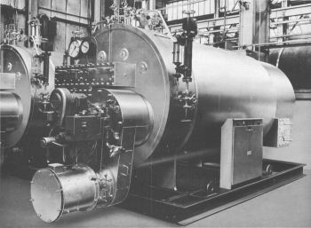
Right: Packaged Ultranomic, arranged for oil firing, ready for despatch from the Works.
Like most packaged boilers, the Paxman types were designed primarily to be oil fired but could be arranged for gas firing. Paxman also developed a coal fired version, the Coalpak. (36) This variant may have been a response to customers' concerns about oil supplies following the 1956 Suez crisis. It is thought only one Coalpak was built: that for a National Coal Exhibition.
The first packaged Ultranomic was built no later than November 1957. Surviving photographs of this date show a small packaged Ultranomic, probably under test in the Works, which was of riveted rather than all-welded construction. In July 1958 a larger packaged Ultranomic was ready for despatch to Whiteley's department store in southwest London.
Paxman's 1958 boiler catalogue offered the 'S' Type packaged boiler. (37) Basically a high velocity dry-back Ultranomic, the most visible difference was that the smokebox was contained within the boiler shell rather than standing proud of the front endplate. So far, no one has been able to recall what the 'S' designation stood for; possibly 'Special'. It looks as if very few 'S' Types were made. They included one built during the summer of 1958 for a Fuel Efficiency Exhibition and two others for the Mobil Oil Company, the latter each 10' diameter x 16' long (contracts 23244/5). There is no reference to the 'S' Type in surviving copies of Paxman's 1960 and 1961 boiler publicity literature.
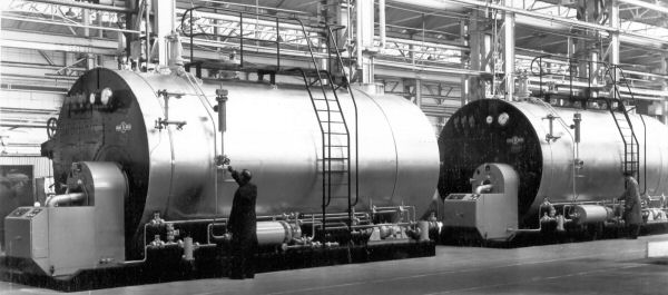
The two S Type packaged boilers for the Mobil Oil Company, being checked in the Works before despatch.
In a 1960 publicity leaflet the oil fired packaged Ultranomic was offered in ten sizes, with outputs of 2,000, 2,500, 3,000, 4,000, 5,000, 6,500, 8,500, 11,000, 14,500 and 19,000 lbs/hour. Ten sizes of this type were also advertised in the 1961 boiler catalogue, but now the outputs of all but the four smallest had been increased to 5,500, 7,150, 9,350, 12,200, 16,000 and 21,000 lbs/hour. (38)
In 1962 Paxman introduced the wet-back Super Ultranomic. An early sale, if not the earliest, of a packaged Super Ultranomic was to the International Flavourings and Fragrances Co Ltd, Haverhill, Suffolk (contract no. 23805). With an output of 5,500 lbs/hr and designed for a working pressure of 245 psig, this boiler had been installed by December 1962. Packaged Super Ultranomics sold in good numbers right up to the end of shell boilermaking at Colchester in 1967.
Reference has been made earlier to packaged boilers being factory-tested before despatch to customers. The June 1958 catalogue section on the 'S' Type says "Arrangements are available for steam testing the complete units in our works" which suggests this was initially an option rather than the norm. Not long after, in about 1960, a boiler test bay was set up at the Works. From then on it became standard practice to test all packaged steam boilers before despatch, including K Type water tube boilers, packaged LPs and Autonomics. The man responsible for most testing was Denis Stevens who recalls handling about three packaged Ultranomics a month during the early 1960s. Normally the task, which included monitoring of fuel, feed water temperature, steam production, and pressure, took about a week. On Monday the boiler was set up in preparation for the actual tests which took place over the following three days before it was taken off the bed on Friday. Testing of the Autonomic could be completed in a relatively short time. (39)
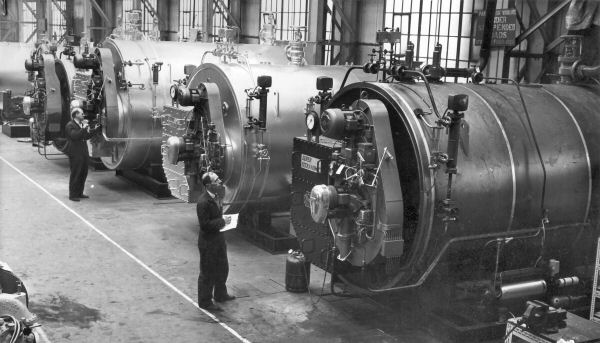
Testing of Super Ultranomics in the test bay at Standard Works in February 1963.
In addition to the testing of packaged boilers before despatch, the test bay facility at Paxman proved very useful for development work. It allowed the Company to try out new ideas for boilers and test new designs of burners and their ancillary equipment; experimental work which could not otherwise have been undertaken.
Packaged boilers saw the start of greater standardisation in what was offered to the market. Up to this time it was normal practice for Paxman's shell boiler customers to be given a range of customisation options to meet individual preferences. An Ultranomic purchaser, for example, could choose whether the furnace was to be offset to the left or the right, specify what fittings he wanted and where valves were to be positioned. When Paxman introduced its American designed water tube boilers little or nothing was offered in the way of customisation options. This philosophy was extended to the Company's other packaged boilers which were built to increasingly standard 'off the peg' specifications in contrast to the bespoke or customised approach adopted for non-packaged types.
![]() back to Index
back to Index
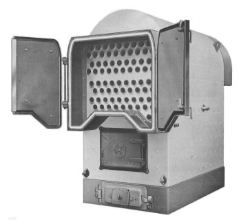 The LP (Low Pressure) Boiler
The 'LP' or Low Pressure boiler appears to have been introduced in 1959. There is no reference to it in the Company's 1958 boiler catalogue which was still advertising the All-Steel Sectional Boiler for central heating applications. A description and specifications of the Paxman LP Boiler are, however, given in a publicity leaflet which bears a print date of February 1959. (40) The LP became a well-established product in the Company's boiler range and sold in good numbers.
Right: LP boiler arranged for solid fuel firing, with ashpit door set in the skirt.
Designed as a compact unit for producing hot water or steam, primarily for heating systems, the LP had a maximum working pressure of 30 psig when first introduced. A year later the maximum working pressure, when used for steam generating purposes, had been increased to 65 psig. The target markets are revealed in a 1962 catalogue which advertised the LP for use in "schools, institutions, hotels, office blocks, flats and factories". A 1965 Paxman Bulletin reported that five had been installed on the twentieth floor of the New Scotland Yard building in London.
The LP was a horizontal self-contained unit of welded construction. It incorporated a water-jacketed furnace of large capacity, designed to promote a high rate of heat transfer from the combustion gases to the boiler water. A treble pass type, it had two nests of smoke tubes, one sitting above the other. The combustion gases passed from the furnace into a water-cooled combustion chamber from where they were directed to the front of the boiler through the lower bank of smoketubes. Entering a collecting box at the front of the boiler, the flow was again reversed, the gases passing through the upper bank of tubes into a smoke outlet box at the rear of the boiler.
Originally the LP was offered for firing by solid fuels, oil or gas. In the catalogue illustration above, the boiler is shown arranged for solid fuel firing, with a large furnace door and an ashpit door. Unlike the oil and gas fired types, this version was mounted on a fabricated steel skirt which served as the ashpit and protected the floor from being damaged by excessive heat.
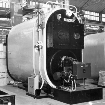 By 1962 some changes had been made to the LP's design. The water jacket had been extended downwards to cover the underside of the furnace. As a result the base of the boiler became rounded in shape, like the top. The boiler was now supported on three legs which lifted the body clear of the floor. This allowed air to circulate underneath, avoiding the risk of heat damaging the foundations and doing away with the need for a refractory base or any special foundations. The three point support system had the well-recognised advantage of providing complete stability and greatly simplified the task of levelling the boiler during installation. In the 1962 publicity there is only reference to oil firing. Perhaps this was due to the lack of demand for solid fuel firing or to solid fuel firing not being practical for the extended water jacket design, or a combination of the two. (41)
Left: Packaged LPS Size 40 boiler for steam duty.
By 1962 the LP was offered in packaged as well as non-packaged form. (41) In packaged form it was supplied fitted with all the necessary ancillary equipment including oil burner, feed water pump and control gear, to make it a fully automatic self-contained unit. As with other packaged types, it became the practice to test packaged LPs in the Works before despatch. The packaged LP is a good example of the influence of the packaged concept on Paxman's boiler design and practice: an influence which had started with the K-Type water tube boiler, manifested itself in the packaged Ultranomic and was now evident in the packaged LP.
The LP was initially offered in eight standard sizes, with outputs ranging from 850,000 to 4,000,000 BThU/hr for hot water duty or 850 to 4,000 lbs/hr for steam duties. In 1961 it was offered in six standard sizes, covering outputs from 1,500,000 to 4,500,000 BThU/hr for hot water duty or from 1,500 to 4,500 lbs/hr for steam duties. (42) By mid-1962 the LP was again offered in 8 standard sizes, ranging from 1,000,000 to 6,000,000 BThU/hr for hot water duty or 1,000 to 6,000 lbs/hr for steam duties. Further details of sizes, dimensions and outputs are given in Appendix H.
The Neopak Steam Generator
The Neopak Steam Generator was advertised in Paxman's 1961 boiler catalogue as "an oil fired, coil type, forced circulation boiler of compact, robust design which is eminently suitable for the small boiler house." (43)
It was stated to be available in three standard sizes, as shown in the table below, for pressures from 80 to 500 psig.
| Model No. | Steam Output from and at 212°F. lbs per hour | Height Overall | Width Overall | Length Overall |
|---|---|---|---|---|
| N3 | 5,000 | 13' 3" | 5' 6" | 13' 6" |
| N4 | 7,000 | 13' 3" | 5' 6" | 13' 6" |
| N5 | 9,000 | 13' 3" | 6' 6" | 14' 6" |
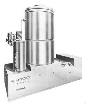 The Neopak was advertised as a form of packaged boiler, tested at the factory before despatch. Fitted with fully modulated automatic oil burners, it was claimed to have a quick response to load change and be capable of raising steam from cold exceptionally rapidly. The complete unit, with its associated equipment such as mountings, feed pumps, oil burner, fans and control equipment, was mounted on a single baseplate. In common with other packaged boilers this made for speedy installation as no special foundations were required and the boiler could quickly be set to work.
Right: Illustration of the Neopak, as used in Paxman publicity literature.
Of all the Paxman publicity literature seen whilst researching for this page, only the 1961 catalogue, and Publication No 1628 have been found to mention the Neopak. The illustration shown here, which appears in both documents, looks as if it was produced from artwork rather than from a photograph. None of the various ex-Paxman boiler people I have spoken to over the years has any recollection of this boiler. One assumes that having got as far as publicly offering the Neopak for sale, the Company must have built one or two development prototypes. However, in the absence of evidence to the contrary, it seems highly unlikely that any production models were made. The Neopak was so different from any previous Paxman design, it could well have been a Peter Hoddinott creation. Perhaps the Neopak was overtaken by the Autonomic on which development commenced in 1962.
![]() back to Index
back to Index
The Super Ultranomic Boiler
Developed from the Ultranomic, the Super Ultranomic appears to have been introduced in 1962. There is no mention of it in the Company's 1961 boiler catalogue but a publicity leaflet entitled 'Super Ultranomic Boilers' carries a March 1962 print date. (44)
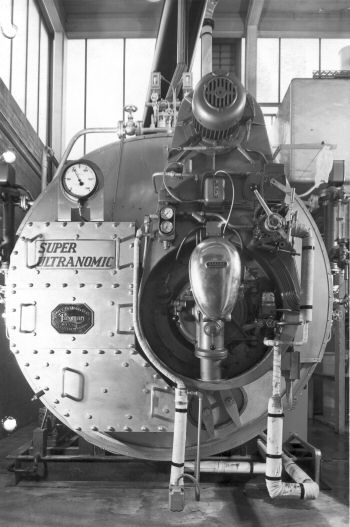 The Ultranomic, like the Economic before it, was a dry-back design. The principal innovation and difference in the Super Ultranomic was its wet-back combustion chamber. The reversal or combustion chamber was surrounded by boiler water so that the heat of the combustion gases, when at their hottest, was transferred to the water. Advantages of the wet-back design put forward in the publicity literature included minimum boiler length and elimination of refractory maintenance in the combustion chamber. With its fully submerged combustion chamber, the boiler imparted all its heat to the water. It eliminated the radiation loss which was inevitable through the refractory lined combustion chamber of a dry-back boiler.
The 1962 leaflet goes on to say: "In recent years perfection of welding techniques, the development of boilers specially designed for oil firing and the rising cost of brickwork, have produced conditions in which the "Wetback" type of combustion chamber is best suited to fulfil modern requirements. Accordingly Paxman's ... have now modified their well tried Ultranomic design to incorporate a 'Wetback' combustion chamber."
Left: Super Ultranomic, in packaged form, installed at International Flavourings and Fragrances, Haverhill, Suffolk in late 1962. Fitted with Saacke rotary cup burner for oil firing.
In summary, the Super Ultranomic can be described as an all-welded, high velocity, treble pass, wet-back shell boiler designed for oil firing. It retained the off-set furnace flue arrangement of the Ultranomic.
The oil burner generally fitted to the Super Ultranomic, unless a customer specified otherwise, was of the rotary cup type supplied by the German firm of Saacke. In this type the fuel oil is fed under low pressure into the smaller end of a fast rotating conical cup. As the film of oil flows to the wider end of the cup, it progressively thins. When it reaches the lip of the cup, the oil is blown off by the forced draught as a fine mist. Alec Burwood, who had much do with the Super Ultranomic, has said that the Saacke was a very good burner, ideally suited to the boiler.
In the 1962 leaflet referred to above, the Super Ultranomic was offered in seventeen standard sizes, for working pressures up to 245 psig. Outputs ranged from 4,000 to 36,000 lbs/hr. Details of individual sizes and dimensions are given in Appendix I. The largest was 11' 3" in diameter and one of these, for hot water duty, was supplied to Pilkington Brothers, the St Helens glass manufacturers, in late 1963 (Contract No. 23996). The Super Ultranomic was a successful design which sold well and a steady stream of orders was received for packaged versions.
One wonders to what extent Ruston, which held the controlling interest in Paxman at the time, influenced Paxman to move from its traditionally favoured dry-back shell boiler design to the wet-back. Ruston had introduced its own highly successful wet-back boiler, the Thermax, in the mid-1930s. The next step in the development of the Thermax and the Super Ultranomic was the Thermax Two which incorporated the best features of each. In late 1965 it was announced to Paxman employees in their house magazine that "The new Thermax Two will gradually supersede the Super Ultranomic in manufacture at Colchester".
The Autonomic Boiler
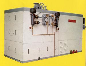 The Autonomic was very much the brainchild of Peter Hoddinott. This innovative boiler was formally launched at a London hotel in March 1965, during Paxman's centenary year, after having been in development for two and a half years. It is hard to imagine a more complete realization of the packaged boiler concept.
The market identified for the Autonomic was small factories, offices, market gardens, and other businesses requiring relatively modest boiler outputs. To meet the needs of such customers and provide a strong competitive edge, the Autonomic embodied a number of novel features. It was designed to be both highly efficient and suitable for mass production so that it could be offered at a low price. A key feature was its compact size. The smallest models were only three feet wide which made them suitable for installation in locations with restricted access and/or space. The Autonomic was fully packaged and self-contained. Not only were the actual boiler and all the ancillaries mounted on a single base: they were totally enclosed within panelling. Installation and setting to work on a customer's premises was a quick, straightforward matter, the unit having been fully tested at the Works prior to despatch.
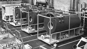 Another selling point was the Autonomic's very rapid steam raising capability with full output achievable in eight minutes from cold. Autonomics were designed to be fully automatic, requiring only a very minimum of attention. Unfortunately in practice they were inclined to be temperamental, requiring a degree of care for reliable operation. One problem was control of the water level in those built for steam generation. For some inexplicable reason the level had a tendency to rise too high, an issue which some people say was never satisfactorily resolved.
The Autonomic was made both as a hot water heater (frame sizes B, C, and D) and as a steam boiler (frame sizes E and F). In essence both types were conventional cylindrical shell boilers of 'wet-back' construction. The water heater was a treble pass design, and the steam boiler a double pass. However the steam boiler incorporated a single pass economiser and its overall efficiency was claimed to be equivalent to that of a treble pass design. The boiler shell was not lagged but insulation was attached to the inner surfaces of the unit's panels. The aim of this arrangement was to allow combustion air to be drawn in through the casing and be pre-heated before reaching the burner. The steady flow of combustion air through the casing also provided some cooling for ancillary equipment enclosed within the unit.
| Autonomic Boiler Dimensions | ||||
|---|---|---|---|---|
| Model | Type | Dimensions: Overall Length x Height x Width | Shell diam. |
Flue diam. |
| 5B, 8B, 10B | Hot Water | 11' x 5' x 3' | 2' 9" | 1' 6" |
| 15CA, 20CA, 25C, 30C | Hot Water | 13' x 5' 8" x 3' 4" | 3' | 1' 6" |
| 40D, 50D, 60D | Hot Water | 13' 10" x 7' 5" x 4' 6" | 4' | 2' |
| 15E, 20E, 25E, 30E | Steam | 12' 7" (15E), 12' 9" (20E and 25E), 12' 10" (30E) x 6' 3" x 5' 4" | 4' | 1' 6" |
| 40F, 50F, 60F | Steam | 13' 10" x 7' 6" x 6' 4" | 5' | 2' |
The output of each model listed in the table above is a multiple of the number preceding its frame size letter. For hot water heaters the output is the prefix number x 100,000 BThUs per hour. For steam boilers the output is the prefix number x 100 lbs of steam per hour, from and at 100° C. Water heaters had a working pressure of 95 psig and steam boilers were designed for a working pressure between 100 and 145 psig.
The Autonomic was oil fired and early versions were fitted with burners manufactured under licence from Dowty Fuel Systems Ltd of Cheltenham. (Dowty Group Services took delivery, in September 1964, of the first Autonomic to be despatched from Colchester. This boiler was put into service at their Cheltenham offices in mid-December, a few weeks before the product's official launch in March 1965.) Experience showed that an advanced 'suction shut down' feature of the Dowty burner offered no real benefits with the Autonomic. As the Autonomic had no refractory quarl near the burner nozzle, it did not suffer the problem experienced with other boilers of lacquering or carbonisation of residual oil on the nozzle tip at the end of each firing cycle. This led Paxman to design and manufacture, specifically for the Autonomic, its own burners which were claimed to be much simpler and mechanically more reliable. The burners were of the pressure jet spill-return type, fed with fuel oil at 300 psi. The smaller hot water heaters had 'on/off' burners whereas those fitted to steam boilers were all fully modulating (i.e. the burner's output adjusted automatically to the load on the boiler). (45) From the comments of Paxman people involved with the Autonomic, one is left with an impression that the burners were not an unqualified success. It could be argued that Peter Hoddinott and Paxman were rather ambitious in attempting to design their own burner. Paxman's knowledge, skills, and many years experience of boiler engineering were not matched by any similar strengths in combustion engineering, a discipline more relevant to the specialist field of oil burner design.
In the months following its launch, sales of the Autonomic exceeded the Company's targets. John Cove, who was Paxman's Marketing Director at the time, recalls that in conjunction with Cyril Jenkins, Boiler Sales Manager, he came to the conclusion that the Autonomic was going to tap into an entirely different market to the larger boilers and so decided on a different marketing strategy. It was decided to take the boiler around the country with a technical as well as a sales team and display it to prospective customers who could see the product and have their questions answered there and then. After the launch in London, similar events were arranged in Manchester, Liverpool, Belfast and Dublin. The routine was always the same. Space was hired in the larger hotels that had ballrooms on the ground floor with access for something the size of an Autonomic boiler. Refreshments were available and the Company advertised the event locally, directed at the type of customers expected to use such boilers. The technical people would give a talk about the boiler and then any questions were answered. John has commented "We had a really good attendance at all these functions and orders came in very quickly for the boilers." Encouraged by the early sales successes Paxman appointed four new regional boiler sales engineers in January 1966. By the end of 1966, less than two years after the launch, about 100 Autonomics had been sold. By the end of the following year around 120 were in operation. Some interesting details of Autonomic sales were published in the June/July 1968 issue of the Paxman Bulletin. Eleven had been supplied to Manchester Corporation for its swimming baths, four had been ordered for Government Training Centres, and a number sold to horticultural nurseries. Other sales were to Esso Petroleum at Southampton, Yorkshire Television (four 60D types), Windsor & Newton at Lowestoft, a jute factory in the Scottish Highlands, and Wilkin & Sons Ltd of Tiptree, the renowned high class jam company (a 30E type). Around this time (1968), as far as ex-Paxman boiler staff can recall, the Company was producing five or six Autonomics a week.
After shell boiler manufacture ended at Colchester in 1967, the Autonomic range was the core of Paxman's boiler business until the Company finally ceased boilermaking in 1969.
![]() back to Index
back to Index
Waste Heat Boilers
Among non-standard products of the Boiler Division were waste heat boilers. They were designed to utilise waste heat from a variety of sources, such as gas turbine and diesel engine exhausts, steel furnaces, incinerators and other industrial plant or processes. Each boiler was purpose built to suit the particular conditions and requirements of the application.
Possibly the largest waste heat boiler built by the Company was one for BP's Isle of Grain oil refinery, in the Thames estuary. There is also surviving evidence of two supplied to the Ford Motor Company's Dagenham Plant, where they were craned up to a highly elevated location in June 1961 (contracts 23388/9), and of a small one made for the Hong Kong Gas Company.
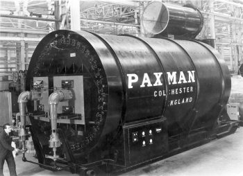 Crude Oil Emulsion Heaters
In the late 1950s Paxman built two gas fired crude oil emulsion heaters for the Kuwait Oil Company (contracts 23220/1). The drawings were mainly the work of Colin Jay. Internally these heaters differed substantially from a boiler or hot water heater. However, externally they bore a strong resemblance to a large shell boiler, as can be seen in the photograph here. Each was 12' wide, x 32' long x 14' 6" high (22' 0" high with its stack), weighed approximately 32 tons, and had a rating of 10,000,000 BThUs/hour.
No one has been able to vouch for the veracity of an amusing story surrounding the despatch of the first heater. Apparently, during its construction, there were various amendments to the design which increased the weight. Also, the original intention had been to send out the heater without its internal refractory bricking and to do the bricking in Kuwait. A change of mind resulted in the bricking being done at the Colchester Works before despatch. Unfortunately someone overlooked the need to recalculate the weight of the finished heater before an attempt was made to load it aboard a ship at Tilbury Docks. According to Paxman folklore the floating crane used for the purpose very nearly capsized!
The Last Five Years
The history of the final years of boilermaking at Colchester was largely shaped by events and decisions elsewhere in the Ruston-Paxman business and some inter-company politics. Ruston & Hornsby of Lincoln had acquired the controlling interest in Davey Paxman in 1940. Although Paxman managed to retain a good deal of autonomy while Edward Paxman was alive, during the years which followed his death in 1949 Ruston increasingly exerted its influence over the management of the Colchester business. Ruston had its own long established and well respected shell boiler business of which the flagship product was the Thermax wet-back boiler. In the late 1950s and early 1960s the Thermax frequently found itself up against competition from Paxman's Ultranomic and then the Super Ultranomic. In the opinion of Paxman people the Super Ultranomic was a superior product, a perception bolstered by the good stream of orders for it. They may well have been correct in their view that Lincoln's Boiler Division was irked by this competition from what they would have seen as a subsidiary company. From a Group point of view it can have made little sense for the two businesses to continue competing head to head in the same market. Another factor in the equation during the early 1960s may have been Ruston's deteriorating financial position. Lincoln had been spending far more on development projects and personnel than could be sustained by profits from its established products. Furthermore, Ruston was incurring very heavy costs of warranty work on its recently launched two-stroke AO diesel engines which were suffering major problems in service. Perhaps Ruston saw the takeover of Super Ultranomic sales not only as a way of controlling the competition which the Super Ultranomic posed to the Thermax, but also as a means of channeling some additional income and profit to its own depleted coffers.
Whatever the real motives of Ruston's senior management, a decision was made in 1963 to re-organise boiler sales. Responsibility for sales of Super Ultranomic (SU) boilers, together with related design and engineering, was transferred to Lincoln in late 1963 or early 1964, while manufacture remained at Colchester. A staff appointment notice at Colchester, dated March 20th 1964, announced a couple of appointments consequent on this re-organisation. Alec Burwood, who at the time was Section Leader in the Boiler Drawing Office, was to be appointed 'SU Boiler Liaison' with effect from 1st April. In that role he was to be the sole channel through which Ruston's Boiler Division at Lincoln would distribute copies of sales orders, drawings, and other relevant technical data to Colchester personnel for those Super Ultranomic contracts to be fulfilled at Colchester. Any technical or manufacturing queries from Colchester staff were to be referred to Mr Burwood who had authority to answer them himself if he was able or otherwise refer them to Lincoln. In this inter-company liaison role he and Dr Ron Hughes had monthly meetings, alternately at Lincoln and Kings Lynn, with Ruston people to review and resolve any issues. The second appointment was that of A B (Tony) Scott, then working in Boiler Sales, to fill the Section Leader post in the D O vacated by Alec Burwood. Mr Scott had substantial previous experience in the Boiler D O, including specific responsibility for the newly introduced water tube and packaged boilers during the latter half of the 1950s. In his new position Mr Scott was to be responsible for the supervision of all D O work relating to boilers other than the Ruston engineered Super Ultranomics.
In 1965 Paxman and Ruston each introduced a new range of boilers to the market. Both products, in quite different ways, were to shape the future course of events at Colchester. In March Paxman launched its Autonomic which has been described earlier on this page. Had it not been for the Autonomic the likelihood is that Paxman would have ceased boiler manufacture about two years earlier than it actually did.
Later in 1965, at the Industry Exhibition, Ruston launched its Thermax Two boiler. This combined the best features of the Thermax and of Paxman's Super Ultranomic, to accomplish rationalisation, and to reduce costs. The Nov/Dec 1965 issue of the Paxman Bulletin explained that "The new Thermax Two will gradually supersede the Super Ultranomic in manufacture at Colchester". The writing was now on the wall for large shell boiler manufacture at Paxman. Very few Economics were being made by this time. Super Ultranomic sales, design and engineering had been transferred to Lincoln more than a year before. Now, the openly declared plan was to phase out the Super Ultranomic in favour of Ruston's new Thermax Two. A cloud of uncertainty descended on those working in the Boiler Division at Colchester.
Any anxieties or concerns about the future could only have increased when in 1966 Ruston and Paxman were acquired by English Electric. Takeovers are invariably accompanied by rationalisation and re-organisation. However, as just mentioned, by the end of 1965 there was plenty of evidence to show the days of large shell boilermaking at Colchester were already numbered. Whether the English Electric takeover hastened the end of this particular activity is difficult to say.
Paxman's long involvement in building large shell boilers came to an end in 1967 when the work was transferred to Ruston. All shell boiler drawings and documentation at Colchester were collected up and sent to Lincoln. The move caused some surprise and a good deal of unhappiness among the staff in Paxman's Boiler Division. They found it difficult to understand and accept the logic of the transfer while they still had plenty of work available and a healthy order book for the Super Ultranomic. After losing this and most of the other boiler work to Lincoln, the main boiler activity left at Colchester was manufacture of the Autonomic range.
There was little time for people to accustom themselves to the new situation before further important changes were in the air. In 1968 English Electric and its constituent companies, including Ruston and Paxman, were absorbed into Arnold (later Lord) Weinstock's GEC (General Electric Company of Great Britain). More rationalisation was inevitable although what was about to happen to boilermaking at Colchester may have occurred regardless of the GEC takeover. By the end of September 1969 manufacture of the Autonomic had been transferred to Ruston's Vulcan Works at Newton-le-Willows in Lancashire and boilermaking finally came to an end at Colchester.
During a century of boilermaking Paxman had acquired a great deal of specialist knowledge and experience, particularly in the field of fabrication. Some of the skills, such as design, draughting, plating and high class welding, were highly relevant to Paxman's rotary vacuum filter business. When boilers finished, several of those who had worked in the Boiler Division, both in the offices and on the shop floor, were offered employment in the Process Plant (later renamed Filtration) Division which continued to build filters on the Standard Works site until April 1989. More about this part of the business can be found on the page Paxman Filters and Filtration.
![]() back to Index
back to Index
Appendix A
Economic Boilers – Dimensions of standard sizes as published in Paxman catalogue 700c (undated, but c.1916-1919).
Paxman Economic Boiler.
With Single or Double Flues.
PRINCIPAL DIMENSIONS OF STANDARD SIZES
| No. | Length of Boiler | Diameter of Boiler | No. of Flues | Diam. of Flues | Internal Heating Surface (squ. feet.) | *Evapor- ation per Hour (lb.) | Approximate Weight of Boiler (cwt.) for a Working Pressure of |
|
|---|---|---|---|---|---|---|---|---|
| 100 lbs. | 120 lbs. | |||||||
| 8 | 6' 5" | 4' 9" | 1 | 2" 3" | 140 | 840 | 43 | 45 |
| 10 | 7' 0" | 5' 0" | 1 | 2" 4" | 174 | 1044 | 48 | 50 |
| 12 | 8' 0" | 5' 0" | 1 | 2" 6" | 234 | 1400 | 57 | 59 |
| 14 | 8' 6" | 5' 0" | 1 | 2" 6" | 248 | 1480 | 59 | 61 |
| 16 | 9' 0" | 5' 3" | 1 | 2" 6" | 276 | 1650 | 66 | 72 |
| 20 | 9' 6" | 5' 6" | 1 | 2" 9" | 324 | 1940 | 78 | 84 |
| 25 | 9' 6" | 6' 0" | 1 | 3" 0" | 393 | 2350 | 90 | 95 |
| 30 | 11' 0" | 6' 3" | 1 | 3" 2" | 478 | 2860 | 118 | 130 |
| 35 | 12' 6" | 6' 6" | 1 | 3" 2" | 565 | 3400 | 130 | 155 |
| 40 | 12' 6" | 7' 0" | 2 | 2" 3" | 665 | 3990 | 164 | 176 |
| 45 | 12' 6" | 7' 6" | 2 | 2" 4" | 772 | 4530 | 182 | 198 |
| 50 | 14' 0" | 7' 6" | 2 | 2" 6" | 890 | 5220 | 200 | 220 |
| 60 | 14' 0" | 8' 0" | 2 | 2" 8" | 1180 | 6960 | 218 | 242 |
| 70 | 14' 0" | 8' 7" | 2 | 2" 10" | 1316 | 7890 | 265 | 290 |
| 80 | 15' 6" | 8' 10" | 2 | 3" 0" | 1509 | 9100 | 310 | 325 |
| 100 | 15' 6" | 9' 9" | 2 | 3" 2" | 2015 | 11500 | 380 | 410 |
* The figures given for the evaporative capacity of each boiler are with feed at 212 deg. Fahr., when burning good coal, and with good draught and stoking. It is of course possible to obtain a much greater evaporation when the draught is ample, and the user is prepared to sacrifice economy to increase the evaporation.
Appendix B
Economic Boilers – Dimensions and outputs of standard sizes as published in Paxman Boiler catalogue Publication 1515, June 1958.
Double Pass Economic Boilers
| No. | Diameter | HIGH VELOCITY | MEDIUM VELOCITY | No. of Flues | Diameter of Flues | ||
|---|---|---|---|---|---|---|---|
| Length O.T.P. | Length Overall | Length O.T.P. | Length Overall | ||||
| 1 | 5' 6" | 10' 0" | 14' 6" | 10' 0" | 13' 6" | 1 | 2' 9" |
| 2 | 6' 0" | 10' 0" | 14' 6" | 10' 0" | 13' 6" | 1 | 3' 0" |
| 3 | 6' 6" | 12' 0" | 17' 0" | 12' 0" | 16' 0" | 1 | 3' 3" |
| 4 | 7' 0" | 12' 0" | 17' 0" | 12' 0" | 16' 0" | 1 | 3' 6" |
| 5 | 7' 0" | 14' 0" | 19' 0" | 14' 0" | 18' 0" | 1 | 3' 6" |
| 6 | 7' 6" | 14' 0" | 19' 0" | 14' 0" | 18' 0" | 1 | 3' 9" |
| 7 | 8' 0" | 14' 0" | 19' 0" | 14' 0" | 18' 0" | 1 2 | 4' 0" 2' 8" |
| 8 | 8' 6" | 14' 0" | 19' 0" | 14' 0" | 18' 0" | 2 | 2' 10" |
| 9 | 9' 0" | 14' 6" | 20' 6" | 16' 0" | 21' 0" | 2 | 3' 0" |
| 10 | 9' 6" | 14' 6" | 20' 6" | 16' 0" | 21' 0" | 2 | 3' 2" |
| 11 | 10' 0" | 14' 6" | 20' 6" | 16' 0" | 21' 0" | 2 | 3' 3" |
| 12 | 10' 6" | 14' 6" | 20' 6" | 16' 0" | 21' 0" | 2 | 3' 6" |
| 13 | 11' 0" | 14' 6" | 20' 6" | 16' 0" | 21' 0" | 2 | 3' 9" |
| 14 | 11' 6" | 14' 6" | 20' 6" | 16' 0" | 21' 0" | 2 | 4' 3" |
| 15 | 12' 0" | 14' 6" | 20' 6" | 16' 0" | 21' 0" | 2 | 4' 6" |
| 16 | 12' 6" | 15' 0" | 21' 0" | 17' 0" | 22' 0" | 3 | 3' 3" |
| 17 | 13' 0" | 15' 0" | 21' 0" | 17' 0" | 22' 0" | 3 | 3' 6" |
| 18 | 13' 6" | 15' 0" | 21' 0" | 17' 0" | 22' 0" | 3 | 3' 9" |
| EVAPORATION FROM AND AT 212° F | ||||
|---|---|---|---|---|
| No. | HIGH VELOCITY Oil Fired | MEDIUM VELOCITY – COAL FIRED | ||
lb /hr. | Stoker Fired lb /hr. | Hand Fired, Forced Draught lb /hr. | Hand Fired lb /hr. | |
| 1 | 2,100 | 2,000 | 2,000 | 2,000 |
| 2 | 2,630 | 2,500 | 2,500 | 2,500 |
| 3 | 3,150 | 3,000 | 3,000 | 3,000 |
| 4 | 4,200 | 4,000 | 4,000 | 4,000 |
| 5 | 5,250 | 5,000 | 5,000 | 5,000 |
| 6 | 6,300 | 6,000 | 6,000 | 5,500 |
| 7 | 7,350 | 7,000 | 7,000 | 6,000 |
| 8 | 8,930 | 8,500 | 8,500 | 7,000 |
| 9 | 10,500 | 10,000 | 9,000 | 8,000 |
| 10 | 12,080 | 11,500 | 9,500 | 8,900 |
| 11 | 13,650 | 13,000 | 10,000 | 9,400 |
| 12 | 15,230 | 14,500 | 10,500 | 10,000 |
| 13 | 16,800 | 16,000 | 11,500 | 11,200 |
| 14 | 18,380 | 17,500 | 12,500 | 12,000 |
| 15 | 19,950 | 19,000 | 12,500 | 12,000 |
| 16 | 22,050 | 21,000 | 12,500 | 12,000 |
| 17 | 24,150 | 23,000 | 12,500 | 12,000 |
| 18 | 26,250 | 25,000 | 12,500 | 12,000 |
NOTE. — The specified duties quoted in this table are based on the use of coal of not less than 11,000 B.T.U.s per lb. calorific value and reasonable ash content and suitable for use with a mechanical stoker where applicable.
Treble Pass Economic Boilers
| DIMENSIONS APPLICABLE TO HIGH OR MEDIUM VELOCITY | |||||
|---|---|---|---|---|---|
| No. | Diameter | Length O.T.P. | Length Overall | No. of Flues | Diameter of Flues |
| 1 | 6' 0" | 10' 0" | 13' 6" | 1 | 2' 6" |
| 2 | 6' 6" | 10' 0" | 13' 6" | 1 | 2' 9" |
| 3 | 7' 0" | 10' 0" | 13' 6" | 1 | 3' 0" |
| 4 | 7' 6" | 10' 0" | 13' 6" | 1 | 3' 3" |
| 5 | 7' 6" | 12' 0" | 16' 0" | 1 | 3' 3" |
| 6 | 8' 0" | 12' 0" | 16' 0" | 1 | 3' 6" |
| 7 | 8' 6" | 12' 0" | 16' 0" | 1 | 3' 9" |
| 8 | 9' 0" | 12' 0" | 16' 6" | 2 | 2' 9" |
| 9 | 9' 6" | 14' 0" | 18' 6" | 2 | 3' 0" |
| 10 | 10' 0" | 14' 0" | 18' 6" | 2 | 3' 2" |
| 11 | 10' 6" | 14' 0" | 19' 0" | 2 | 3' 3" |
| 12 | 11' 0" | 14' 6" | 19' 6" | 2 | 3' 6" |
| 13 | 11' 6" | 14' 6" | 19' 6" | 2 | 3' 9" |
| 14 | 12' 0" | 14' 6" | 19' 6" | 2 | 4' 0" |
| 15 | 12' 6" | 14' 6" | 19' 6" | 2 | 4' 3" |
| 16 | 13' 0" | 14' 6" | 19' 6" | 2 3 | 4' 6" 3' 2" |
| 17 | 13' 6" | 14' 6" | 19' 6" | 3 | 3' 6" |
| 18 | 14' 0" | 14' 6" | 19' 6" | 3 | 3' 10" |
| EVAPORATION FROM AND AT 212° F – As for Double Pass Economic Boilers, see table above. |
|---|
Appendix C
Locomotive Boilers – Dimensions of standard sizes as published in Paxman catalogue 700c (undated, but c.1916-1919).
Locomotive Multitubular Boilers
Raised Fire-Box Type.
Working Pressure 120 lb. per square inch.
PRINCIPAL DIMENSIONS OF STANDARD SIZES
| No. | Length Overall of Boiler | Diameter of Boiler Barrel | Effective Heating Surface (squ. feet.) | *Evaporation per Hour (lb.) | Approximate Weight of Boiler (cwt.) |
|---|---|---|---|---|---|
| 3 | 8' 4" | 1' 11" | 70.6 | 380 | 25 |
| 4 | 9' 6" | 2' 2" | 94.8 | 450 | 28 |
| 5 | 10' 0" | 2' 3" | 105 | 600 | 30 |
| 6 | 10' 2" | 2' 5' | 126.8 | 700 | 31 |
| 7 | 10' 10" | 2' 6" | 153.5 | 800 | 35 |
| 8 | 10' 11" | 2' 8" | 166 | 940 | 40 |
| 10 | 11' 8" | 2' 11" | 199 | 1130 | 50 |
| 12 | 12' 3" | 3' 1" | 232.8 | 1300 | 53 |
| 14 | 13' 0" | 3' 4" | 295.4 | 1740 | 65 |
| 16 | 13' 2" | 3' 4" | 334.3 | 1900 | 72 |
| 20 | 13' 10" | 3' 9" | 400 | 2130 | 80 |
| 25 | 14' 9" | 4' 0" | 464 | 2880 | 104 |
| †30 | 16' 0" | 4' 5" | 550 | 3290 | 133 |
† Note — The 30 horse-power size and upwards are made with flush top.
* The figures given for the evaporative capacity of each boiler are with feed at 212 deg. Fah., when burning good coal, and with good draught and stoking. It is of course possible to obtain a much greater evaporation when the draught is ample, and the user is prepared to sacrifice economy to increase the evaporation.
Appendix D
Ultranomic Boilers – Dimensions and outputs of standard sizes as published in Paxman Boilers, Publication No 1515, June 1958.
Double Pass Ultranomic Boilers
| No. | Diameter | HIGH VELOCITY | MEDIUM VELOCITY | Diameter of Flue | ||
|---|---|---|---|---|---|---|
| Length O.T.P. | Length Overall | Length O.T.P. | Length Overall | |||
| 1 | 5' 6" | 10' 0" | 14' 6" | 10' 0" | 13' 6" | 2' 8" |
| 2 | 6' 0" | 10' 0" | 14' 6" | 10' 0" | 13' 6" | 2' 10" |
| 3 | 6' 6" | 12' 0" | 17' 0" | 12' 0" | 16' 0" | 3' 3" |
| 4 | 7' 0" | 12' 0" | 17' 0" | 12' 0" | 16' 0" | 3' 6" |
| 5 | 7' 0" | 14' 0" | 19' 0" | 14' 0" | 18' 0" | 3' 6" |
| 6 | 7' 6" | 14' 0" | 19' 0" | 14' 0" | 18' 0" | 3' 9" |
| 7 | 8' 0" | 14' 0" | 19' 0" | 14' 0" | 18' 0" | 4' 0" |
| 8 | 8' 6" | 14' 0" | 19' 0" | 14' 0" | 18' 0" | 4' 3" |
| 9 | 9' 0" | 14' 6" | 20' 6" | 16' 0" | 21' 0" | 4' 6" |
| 10 | 9' 6" | 14' 6" | 20' 6" | — | — | 4' 9" |
| 11 | 10' 0" | 14' 6" | 20' 6" | — | — | 5' 0" |
| EVAPORATION FROM AND AT 212° F | ||||
|---|---|---|---|---|
| No. | HIGH VELOCITY Oil Fired | MEDIUM VELOCITY – COAL FIRED | ||
lb /hr. | Stoker Fired lb /hr. | Hand Fired, Forced Draught lb /hr. | Hand Fired lb /hr. | |
| 1 | 2,100 | 2,000 | 2,000 | 2,000 |
| 2 | 2,630 | 2,500 | 2,500 | 2,500 |
| 3 | 3,150 | 3,000 | 3,000 | 3,000 |
| 4 | 4,200 | 4,000 | 4,000 | 4,000 |
| 5 | 5,250 | 5,000 | 5,000 | 5,000 |
| 6 | 6,300 | 6,000 | 6,000 | 5,500 |
| 7 | 7,350 | 7,000 | 7,000 | 6,000 |
| 8 | 8,930 | 8,500 | 8,500 | 7,000 |
| 9 | 10,500 | 10,000 | 9,000 | 8,000 |
| 10 | 12,080 | — | — | — |
| 11 | 13,650 | — | — | — |
NOTE. — The specified duties quoted in this table are based on the use of coal of not less than 11,000 B.T.U.s per lb. calorific value and reasonable ash content and suitable for use with a mechanical stoker where applicable.
Treble Pass Ultranomic Boilers
| DIMENSIONS APPLICABLE TO HIGH OR MEDIUM VELOCITY | ||||
|---|---|---|---|---|
| No. | Diameter | Length O.T.P. | Length Overall | Diameter of Flue |
| 1 | 6' 0" | 10' 0" | 13' 6" | 2' 6" |
| 2 | 6' 6" | 10' 0" | 13' 6" | 2' 9" |
| 3 | 7' 0" | 10' 0" | 13' 6" | 3' 0" |
| 4 | 7' 6" | 10' 0" | 13' 6" | 3' 3" |
| 5 | 7' 6" | 12' 0" | 16' 0" | 3' 3" |
| 6 | 8' 0" | 12' 0" | 16' 0" | 3' 6" |
| 7 | 8' 6" | 12' 0" | 16' 0" | 3' 9" |
| 8 | 9' 0" | 12' 0" | 16' 6" | 4' 0" |
| 9 | 9' 6" | 14' 0" | 18' 6" | 4' 3" |
| 10 | 10' 0" | 14' 0" | 18' 6" | 4' 6" |
| EVAPORATION FROM AND AT 212° F | ||||
|---|---|---|---|---|
| No. | HIGH VELOCITY Oil Fired | MEDIUM VELOCITY – COAL FIRED | ||
lb /hr. | Stoker Fired lb /hr. | Hand Fired, Forced Draught lb /hr. | Hand Fired lb /hr. | |
| 1 | 2,100 | 2,000 | 2,000 | 2,000 |
| 2 | 2,630 | 2,500 | 2,500 | 2,500 |
| 3 | 3,150 | 3,000 | 3,000 | 3,000 |
| 4 | 4,200 | 4,000 | 4,000 | 4,000 |
| 5 | 5,250 | 5,000 | 5,000 | 5,000 |
| 6 | 6,300 | 6,000 | 6,000 | 5,500 |
| 7 | 7,350 | 7,000 | 7,000 | 6,000 |
| 8 | 8,930 | 8,500 | 8,500 | 7,000 |
| 9 | 10,500 | — | — | — |
| 10 | 12,080 | — | — | — |
NOTE. — The specified duties quoted in this table are based on the use of coal of not less than 11,000 B.T.U.s per lb. calorific value and reasonable ash content and suitable for use with a mechanical stoker where applicable.
Appendix E
THE BUILDING OF A BOILER, Worker's Worktime No.8
The text of the above article, published in Paxmans World, No 13, July 1952, pp.26-31, is reproduced verbatim below. The article was accompanied by a number of photographs which it has not been practical to include here.
When you see a boiler, twelve foot diameter, fifteen feet long, being transported to its destination, one does not realise perhaps, the organisation behind its construction, and necessary to maintain a steady flow of work through the shops.
Long before the materials reach the shop floor many hours have been spent designing the boiler and finalising the many details of construction to ensure that the boiler will give many years of service to the benefit of the owners and to the name of "Paxman".
The Drawing Office is responsible for design to meet the particular pressure and steaming conditions required, after which detailed drawings of the boiler and its accessories are made, and these issued to the boiler shop. Its long journey commences with a requisition to Stores from the Planning Department for the boiler end-plates to be delivered to the Hydraulic Press, the shell-plates to the Platers for marking off and the flue-plates to the Flue-Plater.
The boiler end-plates when received are placed in the furnace, brought to a white heat and pressed between blocks of the required dimensions at a pressure of 750 tons, the flue holes pressed and finally levelled.
When cool they are conveyed to the planing machine where the surplus metal is cut off and they are now ready for marking off for Tube and Stay holes.
The Tube holes are then trepanned out on a special purpose machine with twin spindles, special high speed cutters being used.
After this operation the end-plates (back and front), are ready to be assembled on the boiler shell.
By this time the shell-plates, some approximately forty feet long and one inch and one-eighth thick, have been marked out to size, tacking holes drilled, acetylene cut and placed on the Plate Edge Planer for final levelling. The size of these plates has to be very accurate to ensure a perfect fit with the end-plates.
The shell-plates are now rolled to cylindrical form to receive the end-plates in the vertical rolls.
The whole boiler shell is then assembled, complete with manhole seating, etc., and placed on the shell drilling machine; the boiler shell weighing by this time about eleven tons.
When drilled, the boiler is passed to the hydraulic riveters who take the shell completely apart, remove all burrs, reassemble and hydraulic rivet up complete, each rivet being closed at a pressure of eighty to ninety tons; the pressure being sustained for at least seven seconds.
When riveted the Caulkers take over and seal all the joints with pneumatic hammers and the ends of the butt-straps are sealed by the electric welding process.
The hand riveters receive the boiler shell for fitting the flues, which have, in the meantime, been rolled, joggled by spinning, seams electric welded and stress relieved in the annealing furnace at a temperature of 650° C., and then allowed to cool slowly.
When the flues are in position the rivet holes are drilled by a pneumatic drilling machine during which time the riveters are working on those parts which were inaccessible to the hydraulic riveter.
The flue-ends are now riveted by a portable riveting machine which exerts a pressure of 80 tons to each rivet when closing.
The boiler is now ready for tubing and the three hundred tubes are placed in position and expanded in the tube holes to make them perfectly steam tight; the number of tubes differ to the size and required efficiency of the boiler.
The longitudinal stays are fitted and the boiler is ready for testing.
When the testers take over the boiler is filled with water, and a hydraulic pressure of between 200 and 300 lbs./sq.in. is exerted; a tremendous load when one calculates the number of square inches there are in a large boiler.
After a sustained pressure for 30 minutes under the supervision of Mr. C. Brazier, foreman boilermaker, the boiler is emptied, the smoke box fitted and also the combustion chamber, and the boiler lined up for water gauges, etc., by the boiler mounters.
While these are being fitted the painter is at work giving the boiler a final coat of paint, for the transport low loader lorry is generally on the way to collect the boiler by this time.
When this arrives, slings are placed beneath the boiler and the 32-ton load is transferred to the lorry, the familiar labels are affixed and the boiler moves out complete with fittings and mountings to meet the Police escort at the works gates.
For all the above operations to be carried out, it is obvious that all the parts and sections of the boilers have to be at hand when required, otherwise it means the gangs of boilermakers would be waiting for work. This is no mean task as there are always 10 to 12 horizontal boilers in addition to hot water and vertical boilers being progressed through the shops at one time.
Mechanical breakdowns have to be serviced immediately, transport kept up to scratch and so on.
Appendix F
K-Type Water Tube Boilers – Sizes and outputs as published in Paxman Boilers, Publication 1515, June 1958, p.17, Paxman K Type Water Tube Boilers, Publication 1538, July 1958, p.5 and Paxman Boilers, Publication 1645, February 1961, p.23.
| PACKAGED K TYPE BOILER DETAILS | ||||
|---|---|---|---|---|
| Boiler Size | Heating Surface | Evaporation lbs per hour | Approx. Weight for Working Tons | |
| Square Feet | Square Metres | |||
| 75 | 375 | 31.8 | 2,500 | 10 |
| 100 | 500 | 46.5 | 3,500 | 11 |
| 150 | 750 | 69.7 | 5,000 | 12½ |
| 200 | 1,000 | 92.9 | 6,750 | 14 |
| 250 | 1,250 | 116.1 | 8,500 | 15½ |
| 300 | 1,500 | 139.3 | 10,000 | 18 |
| 350 | 1,750 | 162.6 | 11,500 | 18 |
| 400 | 2,000 | 185.8 | 13,500 | 20½ |
| 450 | 2,250 | 209.0 | 15,000 | 23½ |
| 500 | 2,500 | 232.2 | 17,000 | 26½ |
| NON-PACKAGED K TYPE BOILER DETAILS | ||||
| 600 | 3,000 | 278.7 | 20,000 | |
| 700 | 3,500 | 325.2 | 23,000 | |
| 800 | 4,000 | 371.6 | 27,000 | |
| 1,000 | 5,000 | 464.4 | 33,000 | |
Appendix G
VL Water Tube Boilers – Sizes and outputs as published in Paxman Boilers, Publication 1515, June 1958, p.19.
| GAS OR OIL FIRED VL TYPE BOILER DETAILS | ||||||
|---|---|---|---|---|---|---|
| Boiler Size | Heating Surface | Evaporation lbs per hour | Length ft. in. | Width ft. in. | Height ft. in. | |
| Square Feet | Square Metres | |||||
| 200 | 1,063 | 98.75 | 6,600 | 18' 6" | 8' 3" | 11' 0" |
| 250 | 1,342 | 124.67 | 8,250 | 19' 3" | 8' 9" | 11' 9" |
| 300 | 1,605 | 149.10 | 10,000 | 20' 9" | 8' 9" | 12' 3" |
| 350 | 1,752 | 162.76 | 11,500 | 20' 9" | 9' 3" | 12' 9" |
| 400 | 2,037 | 189.24 | 13,250 | 22' 3" | 9' 3" | 13' 3" |
| 500 | 2,500 | 232.25 | 16,500 | 23' 7" | 9' 9" | 13' 6" |
| 600 | 3,075 | 285.67 | 20,000 | 25' 6" | 9' 9" | 14' 1" |
| 700 | 3,500 | 325.15 | 23,000 | 27' 0" | 9' 9" | 15' 6" |
Appendix H
LP Boilers – Sizes and outputs as published in Paxman L.P. Boiler, Publication No 1593, February 1959.
| SIZES AND OVERALL DIMENSIONS | |||||||
|---|---|---|---|---|---|---|---|
| Size | Heating Surface squ. ft. | Width | Height excluding skirt | Overall Length | Length over Tube Plates | BThUs/Hr | lbs of Steam per hour |
| 200 | 196 | 3' 0" | 5' 5" | 6' 7" | 4' 7" | 850,000 | 850 |
| 250 | 244 | 3' 0" | 5' 5" | 7' 6" | 5' 6" | 1,000,000 | 1,000 |
| 350 | 333 | 3' 6" | 5' 9" | 8' 9" | 6' 5" | 1,500,000 | 1,500 |
| 450 | 440 | 4' 0" | 6' 10" | 8' 11" | 6' 4" | 2,000,000 | 2,000 |
| 600 | 587 | 4' 0" | 6' 10" | 10' 11" | 8' 4" | 2,500,000 | 2,500 |
| 700 | 685 | 4' 8" | 6' 11" | 10' 9" | 8' 2" | 3,000,000 | 3,000 |
| 800 | 783 | 4' 8" | 6' 11" | 11' 10" | 9' 3" | 3,500,000 | 3,500 |
| 1000 | 978 | 4' 8" | 6' 11" | 14' 1" | 11' 6" | 4,000,000 | 4,000 |
Publication No 1593 1st Revision, of January 1960, shows details of sizes 350 to 1,000. Outputs and lengths published in the revision are as above, but there are some changes to height and width dimensions.
LP Boilers – Sizes and outputs as published in Paxman Boilers, Publication No 1645, February 1961, p.25.
| OUTPUTS, RATINGS & OVERALL DIMENSIONS | ||||||
|---|---|---|---|---|---|---|
| Model No. | Steam Output from and at 212° F. lbs/hr | Rating B.Th.U.s/Hr | Height excluding skirt | Width | Length over Tubeplates | Length Overall |
| 350LP | 1,500 | 1,500,000 | 7' 2" | 3' 9" | 6' 3" | 8' 5" |
| 450LP | 2,000 | 2,000,000 | 7' 3" | 4' 5" | 6' 5" | 8' 10" |
| 600LP | 2,500 | 2,500,000 | 7' 3" | 4' 5" | 8' 4" | 10' 9" |
| 700LP | 3,000 | 3,000,000 | 8' 0" | 5' 1" | 8' 2" | 10' 7" |
| 800LP | 3,500 | 3,500,000 | 8' 0" | 5' 1" | 9' 3" | 11' 8" |
| 1000LP | 4,500 | 4,500,000 | 8' 0" | 5' 1" | 11' 6" | 13' 11" |
LP Boilers – Sizes and outputs as published in Paxman LP Boilers, Publication No 1706 (R), June 1962.
| LPS Series - outputs for steam generation - lbs of steam per hour from and at 212° F. | |||||||
|---|---|---|---|---|---|---|---|
| LPS. 10 | LPS. 15 | LPS. 20 | LPS. 25 | LPS. 30 | LPS. 35 | LPS. 45 | LPS. 60 |
| 1,000 | 1,500 | 2,000 | 2,500 | 3,000 | 3,500 | 4,500 | 6,000 |
| LPW Series - Hot Water Heater outputs - BThUs per hour. | |||||||
| LPW. 10 | LPW. 15 | LPW. 20 | LPW. 25 | LPW. 30 | LPW. 35 | LPW. 45 | LPW. 60 |
| 1,000,000 | 1,500,000 | 2,000,000 | 2,500,000 | 3,000,000 | 3,500,000 | 4,500,000 | 6,000,000 |
Appendix I
Super Ultranomic Boilers – Sizes and outputs as published in Paxman Super Ultranomic Boilers, Publication No. 1705, March 1962.
The data shown below was for boilers with a working pressure of 145 psig. Other pressures were available up to 245 psig.
| Size | Evaporation lbs per hour | Length Overall | Boiler Diameter | Dry Weight Tons |
|---|---|---|---|---|
| 1 | 4,000 | 15' 4" | 6' 6" | 7.3 |
| 2 | 4,750 | 15' 4" | 6' 6" | 7.5 |
| 3 | 5,500 | 15' 4" | 6' 6" | |
| 4 | 6,500 | 15' 10" | 7' 6" | |
| 5 | 7,500 | 15' 10" | 7' 6" | |
| 6 | 8,500 | 15' 10" | 7' 6" | |
| 7 | 9,500 | 17' 4" | 7' 6" | |
| 8 | 10,500 | 17' 7" | 8' 0" | |
| 9 | 12,000 | 17' 7" | 8' 0" | |
| 10 | 14,000 | 18' 7" | 9' 0" | |
| 11 | 16,000 | 18' 7" | 9' 0" | |
| 12 | 18,000 | 18' 7" | 9' 0" | |
| 13 | 21,000 | 19' 4" | 10' 3" | |
| 14 | 24,000 | 19' 4" | 10' 3" | |
| 15 | 28,000 | 19' 10" | 10' 3" | |
| 16 | 32,000 | 19' 10" | 11' 3" | 28.5 |
| 17 | 36,000 | 19' 10" | 11' 3" | 29.5 |
References:
1. Steam and the Road to Glory - The Paxman Story, Andrew Phillips, Hervey Benham Charitable Trust 2002 (ISBN 0 9529360 1 1), p.66.
2. ibid p.75.
3. ibid p.39.
4. ibid p.227.
5. 50 Years, 1933-1983, Association of Shell Boilermakers, published by the Association in 1983 to mark its 50th anniversary.
6. Welding and Fabrication for World Industry, Paxman Publication No 1509, February 1957. Also revised version of this, Paxman Publication No 1696, February 1961.
7. op. cit. Steam and the Road to Glory, pp.176, 229.
8. Paxman Boilers & Superheaters, Paxman Publication No 700c, undated but c.1916-1919, p.7C.
9. Paxman Boilers, Paxman Publication No 1515, June 1958, pp.5, 7.
10. op. cit. Paxman Boilers & Superheaters, Paxman Publication No 700c.
11. Paxman Copy Order Book No 6. Order Nos 16215 and 16216, of 2nd June 1926, are each for a "4 Section Hot Water Boiler".
12. Paxman All-Steel Sectional Boilers, Paxman Publication No 1048, undated but post-1932.
13. op. cit. Paxman Boilers, Paxman Publication No 1515, p.20.
14. Paxman All-Steel Sectional Boilers, Paxman Publication No 1537, January 1960.
15. Paxman's World, No 11, May 1951, p.29.
16. Visit to the Works of Davey, Paxman & Co Ltd, Colchester by the Contractors to M.O.S. 23rd June 1945., Paxman Publication No 1155A, pp.24-26.
17. Colchester and Davey Paxman & Co Ltd, Paxman Publication 1174-R, March 1948, p.37.
18. The London Gazette, 12 July 1946, p.3629. Peter Hoddinott's promotion from Lieutenant Commander (E) to Commander (E), Royal Navy.
19. Paxman Works Bulletin, December 1960.
20. Paxman Boilers, Paxman Publication No 1353, undated but c.1953.
21. op. cit. Paxman Boilers, Paxman Publication No 1515, pp.2, 6, 8.
22. As related to me by Jim Edwards during a detailed discussion on 19th March 2003 about his career and recollections.
23. op. cit. Steam and the Road to Glory, p.228.
24. op. cit. Paxman Boilers, Paxman Publication No 1515, pp.15-17; Paxman K Type Water Tube Boilers, Paxman Publication No 1538, July 1958; Paxman Boilers, Paxman Publication No 1645, February 1961, pp.22-23.
25. Paxman K Type Water Tube Boilers, Paxman Publication No 1538, July 1958, back cover and p.2.
26. Paxman Water Tube Boilers, Paxman Publication No 1697, May 1961.
27. Paxman Water Tube Boilers, Paxman Publication No 6003, August 1964.
28. Paxman Bulletin, August 1966.
29. Paxman Boilers, Paxman Publication No 1645, February 1961, p.21.
30. Paxman VL Type Water Tube Boilers, Paxman Publication No 1406R, October 1956, pp.9-11.
31. op. cit. Paxman Boilers, Paxman Publication No 1515, pp.18-19.
32. op. cit. Paxman Boilers, Paxman Publication No 1645, pp.20-21.
33. op. cit. Paxman Water Tube Boilers, Paxman Publication No 6003.
34. op. cit. Paxman Boilers, Paxman Publication No 1645, p.20.
35. op. cit. Paxman Water Tube Boilers, Paxman Publication No 1697, inside back cover.
36. Paxman Coalpak Boiler, Paxman Publication No 1629, February 1960; op. cit. Paxman Boilers, Paxman Publication No 1645, pp.6-7.
37. op. cit. Paxman Boilers, Paxman Publication No 1515, p.14.
38. Paxman Oil Fired Packaged Boiler, Paxman Publication No 1560 (2nd Revision), March 1960; op. cit. Paxman Boilers, Paxman Publication No 1645, p.8-9.
39. As related to me by Denis Stevens, during a discussion on 3rd February 2003 about his work at Paxman.
40. Paxman L.P. Boiler, Paxman Publication No 1593, February 1959.
41. Paxman L.P. Boilers, Paxman Publication No 1706 (R), June 1962.
42. Paxman Boilers, Paxman Publication No 1645, February 1961, pp.24-25.
43. ibid. p.29.
44. Super Ultranomic Boilers, Paxman Publication No 1705, March 1962.
45. Autonomic Sales Engineers' Handbook, (2nd Revision), October 1967.
Acknowledgements: Writing this page involved a steep learning curve for someone who joined Paxman sixteen years after boilermaking ceased at Colchester and who previously knew absolutely nothing about industrial boilers. Fortunately some of those who formerly worked in Paxman's boiler business were willing to spend a good deal of time and effort in explaining the basics and sharing their recollections. Many of the questions put to them were about products and events of at least forty years ago and in some cases more than fifty years ago. My mentors worked hard to recollect the facts as best they could but after such a length of time allowance must be made for the possibility that memories of some details may not be entirely accurate. Between us we have done our best to strive for accuracy, checking where possible with contemporary documents.
Particular thanks are due to the following for their invaluable and generous help: A W (Alec) Burwood (Paxman 1949-74), A B (Tony) Scott (Paxman 1946-69), F H (Fred) Frost (Paxman 1941-88), J (Jim) A Edwards (Paxman 1933-81), Roy Beardwell, Reg Hart (Electrical), Denis Stevens (boiler test-beds) and A E (Alf) Garner (Paxman 1940-51).
© Richard Carr 2011
Page updated: 15 DEC 2011