
Paxman's Hi-Dyne Engine for Rail Traction
The Hi-Dyne Principle
The Paxman 'Hi-Dyne' engine was developed for diesel-mechanical rail traction. Diesel engines normally produce their maximum power at full engine speed and proportionally less power at lower rotational speeds. In rail traction the need is for high power at low track speeds to provide good acceleration when moving off and to maintain speed on rising gradients. This is not a problem with diesel-electric and diesel-hydraulic transmissions which allow engines to be run at high rotational speeds over the full range of track speeds, making maximum power available even at the lower end of the range. They are, however, more complex and expensive, and less efficient, than a diesel-mechanical transmission.
The Hi-Dyne was designed to produce the same or similar power output throughout its engine speed range. The aim was to achieve increased torque as engine speed decreased, thus giving the ideal tractive effort curve and making it practical to replace electric and hydraulic transmissions with relatively simple mechanical gearboxes. To achieve the 'constant horsepower' characteristic the quantity of fuel and air fed into each cylinder had to be increased as engine speed decreased. Fuelling was controlled by a modified form of simple fly weight governor linked to the fuel control rod. The force exerted by the governor was varied by the throttle lever which determined the available power output, not the speed of the engine. The latter varied according to the tractive resistance (load) within the operating speed range for the engine, whatever the throttle position. The main challenge was to feed sufficient air into the cylinder at low speeds for proper combustion of the increased amount of fuel injected. The solution adopted in the Hi-Dyne engine was to use a turbocharged engine with the turbocharger matched to give a high rate of air flow at the lowest engine speed.
An article about the Hi-Dyne appeared in Paxman's Colchester Newsletter No 7, issued in September 1954. (1) The text is reproduced lower down this page as Appendix A. A detailed technical paper about the principles of the Hi-Dyne and the Company's early experience with it, The Paxman "Hi-Dyne" Diesel Engine for Rail Traction, was written in 1956 by David Pearce, Paxman's Chief Research Engineer at the time. (2) The text of the paper is reproduced lower down this page as Appendix B.
Hudswell Clarke's Locomotive 'Enterprise'
A Hi-Dyne was first installed in a 48 ton 0-6-0 experimental shunter 'Enterprise', built by Hudswell, Clarke & Co of Leeds in 1954 (Hudswell Clarke Works No D810). Trials of the locomotive commenced no later than the autumn of 1954 and the January 1955 issue of Diesel Railway Traction reported that 'Enterprise' "has worked with considerable success during the past few months at various collieries and industrial sites". (3).
Enterprise's Engine
The history of the engine installed in 'Enterprise' is not straightforward. The six-cylinder vee form RPH Series 1, Serial No 100017/6, was built originally under Paxman Contract No 53075 to fulfil an order received from Hudswell Clarke on 9th January 1952. According to Paxman records, the engine was for a locomotive to be called 'Yorkist'. No evidence has been found of a locomotive of this name and it is thought the name 'Yorkist' must have been dropped in favour of 'Enterprise'. The engine built under this contract was naturally-aspirated, with a maximum rating of 275 bhp at 1,250 rpm, and was despatched on 18th August 1953. The contract documentation notes it was to drive a fluid mechanical gearbox through a Holset flexible coupling. The documentation also notes that the engine was subsequently to be converted to a 'constant HP' (i.e. Hi-Dyne) build. It is thought the engine was ordered first in its naturally-aspirated form, to be run in the locomotive with a conventional transmission, to form a basis for comparison with the performance of the Hi-Dyne arrangement.
Paxman Contract 53602, received from Hudswell Clarke on 3rd June 1953, was for conversion of the engine supplied under Contract 53075 to a 'constant HP' build. This involved converting the engine from being naturally-aspirated to being turbocharged, and designing a suitable constant power control system in conjunction with Fluidrive Engineering Ltd which was to supply the Dual Fluidrive gearbox. The contract specified that the engine was to be returned to Colchester for conversion and despatched back to Hudswell Clarke within one month. A Brown Boveri VTR 160 turbocharger was fitted and a specially developed governor to give a constant power output of 210 bhp at all rotational speeds between 735 and 1,250 rpm. The converted engine was sent to Hudswell Clarke on 26th March 1954. In this second contract the locomotive is still referred to as 'Yorkist'.
Enterprise's Transmission Arrangement
Although the Hi-Dyne could be used with any normal type of mechanical gearbox, Paxman favoured the Fluidrive system, developed and built by the Fluidrive Engineering Co Ltd, because it overcame a major drawback of the conventional gearbox: the momentary loss of traction whilst changing gear. 'Enterprise' was fitted with a three-speed Dual Fluidrive gearbox, comprising a pair of fluid couplings directly connected to the engine. Contract No 53602 quotes the gearbox ratios as 3.2 : 1 for low gear, 1.8 : 1 for second and direct drive for top. A Synchro-Self-Shifting (SSS) clutch was used to control the reaction member. In addition to the three-speed box, there was a low and high ratio gearbox combined with the reverse gearbox and final drive. The arrangement gave 'Enterprise' six speeds, quoted in Contract No 53602 as 4.6, 8.2 and 14.6 mph in low ratio and 9.5, 16.9 and 29.9 mph in high ratio.
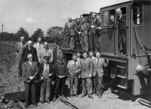
Representatives of Paxman and Regulateurs Europa with Enterprise on test on the old Stockton - Darlington
line circa 1956. Tests were carried out using a dynamometer car and a load comprising forty 40-ton coal trucks
on which the brakes were adjusted to control drawbar load.
What Happened to 'Enterprise'?
Surviving Paxman records tell us little about the subsequent history of 'Enterprise'. It would appear its engine was returned to Colchester for repair or overhaul under Paxman Contract No RO143399, after which it was despatched back on 6th May 1955. Spares were regularly sold for the engine up to 1961 but then there is a gap until 1972. There is no Paxman record showing whether the locomotive or its engine was ever sold on by Hudswell Clarke.
There is information on the internet about 'Enterprise', some of which needs corroboration and confirmation. This includes a photograph with notes: "No.D810 of 1958, "Enterprise". The loco worked at various collieries and steel works. D810 is pictured in "as withdrawn" condition, at the Ashford Steam Centre, 10/72, the last time it's existence is recorded." We know Enterprise was built in 1954, not 1958. In the 1972 photograph the locomotive looks to be in a very poor state. Responses to enquiries suggest a former Managing Director of the Mid-Hants Railway, Margaret ?, may have acquired 'Enterprise' in the late 1970s or early 1980s and left it with the South Devon Railway for "safe keeping". Then there is a photograph of 'Enterprise' at Buckfastleigh, on the SDR, in 1986. Here it looks to be in a much better state than in the 1972 picture. Subsequently it was sold to C F Booth for scrapping. A further photograph is of D810 at Booth's Rotherham Yard (about half-way down page) in 1992. It is believed 'Enterprise' was scrapped there, either in 2004 or in 2009. Any other information on the history of 'Enterprise' would be appreciated.
A Final Comment on 'Enterprise'
It has been noted above that when the 6RPH engine was first supplied to Hudswell Clarke, in its naturally-aspirated form, it had a maximum rated output of 275 bhp at 1,250 rpm. After conversion to Hi-Dyne build the maximum rating was 65 bhp less, only 210 bhp at engine speeds between 735 and 1,250 rpm, despite the addition of a turbocharger. Don Meiklejohn has observed that although the Hi-Dyne build did provide more power at lower engine speeds, it would still offer less power than the same engine in conventional build, used at its maximum power rating, in a locomotive with an electric or hydraulic transmission which could transmit this power over a large proportion of the locomotive speed range.
Although Hudswell Clarke advertisements of 1958 and 1959 stated that 'The "Enterprise" series can now be supplied in horse powers up to 1200', the only Hi-Dyne locomotives ever built were 'Enterprise' and those for Sierra Leone described below.
Sierra Leone Government Railway
Other than 'Enterprise', described above, only twenty four Hi-Dyne locomotives were built. They were the 120 Class mixed-traffic 2-8-2 locomotives for the 2' 6" gauge Sierra Leone Government Railway (SLGR) and, like 'Enterprise', were built by Hudswell, Clarke.
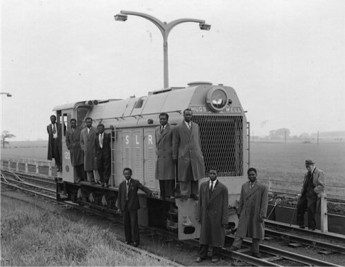
The picture above shows the first Hi-Dyne locomotive for Sierra Leone, No 120, being demonstrated on the 2' 6" gauge line of Ledstone Luck Colliery, near Castleford in Yorkshire. It was an ideal section of track for Hudswell Clarke to test and demonstrate its locomotives of this smaller gauge.
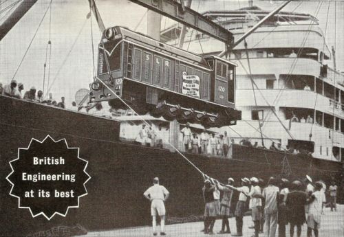
Sierra Leone locomotive No 120 being unloaded at Freetown Docks.
Picture taken from a 1958 Hudswell Clarke advertisement.
The engines supplied for these locomotives were Hi-Dyne versions of Paxman's six-cylinder YHXL Mk 3, not of the 6RPHXL fitted in 'Enterprise'. The 6YHXL engines were a little more powerful than the 6RPHXL, with a rating of 225 rather than 210 bhp. They were also designed to produce their 225 bhp power output over a slightly wider engine speed range: from 650 to 1,250 rpm, instead of from 735 to 1,250 rpm in the case of the 6RPHXL Hi-Dyne. To achieve this they had fuel injection advance and retard and an auxiliary Rootes type supercharger to supplement the Napier turbocharger fitted. A specially modified governor, the 305G Hi-Dyne governor, maintained the constant power output by regulating the fuel injection pump rack position and thus the quantity of fuel injected into the cylinders. These were the only YH Hi-Dyne engines ever built and the only 6-cylinder YH engines ever supplied for rail traction duty.
The transmission system comprised a Vulcan Sinclair Dual Fluidrive transmission unit and a final reduction gearbox supplied by Bostock and Bramley.
The twenty four locomotives were built by Hudswell Clarke in fulfilment of three or four sets of orders.
The first set of orders was for eight locomotives, Hudswell Clarke Works Nos D1044 to D1051 (SLGR Nos 120 to 127), completed in 1958. The engines for these were built under Paxman Contract Nos 55096 to 55103, raised on 15th November 1956. They had Serial Nos 560035/1 to /3 and /6 to /10 and were despatched between 13th June and 18th September 1958.
 The second set of orders was for the eight locomotives, Hudswell Clarke Works Nos D1142 to D1149 (SLGR Nos 128 to 135), built in 1959. The engines for these were built under Paxman Contract Nos 55721 to 55728, raised on 7th July 1958. They had Serial Nos 580013/3 to /8, /10 and /11 and were despatched between 6th February and 3rd July 1959.
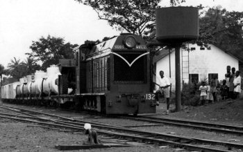
Right: Sierra Leone Hi-Dyne Locomotive No 132 in traffic.
A further eight locomotives were ordered but there is some question as to whether all eight were ordered at the same time or whether an order originally for six was later increased to eight, or whether two orders were placed: one for six locomotives and a later one for two. The six locomotives, Hudswell Clarke Works Nos D1218 to D1223 (SLGR Nos 136 to 141), were completed in 1960-61, and the last two, Hudswell Clarke Works Nos D1229 and D1230 (SLGR Nos 142 and 143), in 1961. The engines for the first six were built under Paxman Contract Nos 56271 to 56276, raised on 1st March 1960. These had Serial Nos 580019/1 and /4 to /8 and were despatched between 16th September and 2nd December 1960. The engines for the last two locomotives were built under Paxman Contract Nos 56361 and 56362, raised on 21st July 1960. They had Serial Nos 580030/2 and/3 and were despatched on 10th February 1961.
The Crown Agents placed an order for a spare Hi-Dyne engine for Sierra Leone. Built under Paxman Contract No 56292, raised on 29th April 1960, this had the Serial No 580030/1 and was despatched on 5th December 1960.
The Crown Agents subsequently ordered two more 6YHXL engines for Sierra Leone. These were of conventional build, fitted with conventional governors, intended for conversion of two of the Hi-Dyne locomotives to a conventional engine and transmission arrangement. The engines were supplied under Paxman Contract Nos 57820 and 57821, raised on 6th August 1963. Each with a rated output of 245 bhp at 1,250 rpm, they had Serial Nos 630017/1 and /2 and were despatched on 24th and 29th April 1964. Two other Paxman contracts related to the locomotive conversions were Nos 57822 and 57823. These were with the Drewry Car Company Ltd for the fitting of fluid couplings, shafts, accessory drives and exhaust systems. Also to be supplied under these latter contracts were combined underbases on which the engines, and the new transmissions supplied by the Drewry Car Company, would sit.
The locomotives supplied to Sierra Leone were not a resounding success. The Annual Report of the Sierra Leone Railway Department for 1959-60 includes the following:
"… a large number of mechanical failures have occurred with the 120 Class Locomotives and the improved availability and reliability which was anticipated from their use has not been fully realised. A considerable number of major and minor modifications have been necessary and it is hoped that these modifications will be effective and raise the percentage of availability to a reasonable figure. Visits to site have been made during the year by Mr D.C. Brown, Chief Mechanical Engineer of the Crown Agents, Mr D. Pearce, Chief Engineer of Davey Paxman Limited, Mr Stent, Chief Development Engineer of Davey Paxman Limited and Messrs. Lambert and Walters, Technical Director and London Representative, respectively, of Hudswell Clarke Company Limited. Both Hudswell Clarke and Davey Paxman have provided resident Service Engineers throughout the year to carry out modifications and information on tests carried out on site and in Davey Paxman’s works is constantly being exchanged with the Crown Agents. The two latest major modifications, designed to reduce excessive cylinder liner wear and sludging of engine lubricating oil which have been experienced, have been fitted to all locomotives in service, but it is too early yet to state if these will be effective in eliminating the troubles. The manufacturers are confident they will eliminate these and other faults eventually, but Management’s concern is to eradicate them at the earliest possible time, so that the full benefits of the lower fuel and operating costs to diesel traction may be obtained now and not at some indefinite time in the future."
Surviving Paxman records suggest that spares for the Sierra Leone locomotives ceased to be supplied around 1973. This is consistent with the closure of the Sierra Leone Government Railway in 1974.
Surviving SLR Class 120 Locomotives
Two of the twenty-four Class 120 locomotives built for SLR are in preservation and on display at the Sierra Leone National Railway Museum, Freetown, Sierra Leone. One is No 123 (Hudswell Clarke Works No D1047), one of the first batch of eight Class 120 locomotives, completed in 1958. It is a 'Modified Class 120 Locomotive', one of the two locomotives rebuilt with the conventional 6YHXL engines supplied by Paxman in April 1964 and the Drewry Car Co transmissions. In a photograph of the locomotive taken c.2015/2016 the cylinder heads on at least one bank of the engine are missing.
The other survivor is No 133 (Hudswell Clarke Works No D1147?), one of the second batch of eight Class 120 locomotives built in 1959. During its working life No 133 was re-engined with a Gardner 8L3 engine which is in the preserved locomotive.
William Bickers-Jones has a record of two Gardner engines being supplied to the Drewry Car Co and thinks that the SLR rebuilt a total of four Class 120 locomotives with conventional engines and conventional transmissions: two with conventional Paxman 6YHXL engines and two with Gardner 8L3 engines. That appears to be the most logical conclusion to draw from the information currently available.
Appendix A
Colchester Newsletter No 7. A Publication of the Ruston-Paxman Group
(September 1954)
THE HI-DYNE ENGINE
The "constant horse-power" engine is, as will be readily appreciated, an ideal towards which many manufacturers have striven for a great number of years — high power at low speeds being the principal point on which the steam engine has held any advantage over the compression ignition unit. The ideal arrangement is, without doubt, an engine with a wide speed range, the torque of which rises as the engine speed falls, for if the speed range was wide enough and the rise in torque steep enough, then a single fixed gear ratio would be adequate.
Of the many duties which require an engine to have a wide speed range, road and rail transport form the largest group. It has been normal practice to develop an engine to give its maximum power at full engine speed, and under these circumstances the engine torque remains approximately constant over the speed range.
In the case of locomotive traction in particular, this characteristic of "constant torque" is far from ideal. As the resistance of the vehicle increases, for example on a rising gradient, so more torque is required at the driving wheels, and with a given gear ratio and a "constant torque engine" the road speed will fall at an increasing rate. Hence it is necessary to employ a change speed gearbox. In general, a greater acceleration is required at low vehicle speeds, and this can only be obtained if a greater torque is available at driving wheels.
Diesel-electric or diesel-hydraulic locomotives use forms of transmission which give an infinitely variable gear ratio, enabling the engine to run nearer to constant speeds and maximum powers over the whole range of road speed.
Locomotives with diesel-mechanical transmission produce a "stepped" tractive effort, a relatively small change in train resistance causing a relatively large change in road speed, and suffer from the normal difficulties of relating road speed to gear ratio unless the number of gear ratios available are increased considerably — which produces parallel problems of cost, size and complexity.
In order that a diesel-mechanical locomotive should produce the ideal type of tractive effort curve, such as that produced by the diesel-electric loco, it will be appreciated that the gear ratio would have to vary inversely with road speed, the engine running at constant speed and constant output.
With a fixed gear ratio and variable speed engine, however, the engine torque must vary inversely with road speed.
No ordinary diesel engine can compete with a steam engine in giving high torque at zero, or at very low rotational speeds, and the speed range over which it can maintain a reasonably high constant output will be comparatively limited. The theoretical extension to infinitely high torque at infinitely low speed is, fortunately, not even desirable, since the limit of wheel adhesion limits the tractive effort that can be used.
The "constant horsepower" type of engine, whose torque curve falls with rising speed does, however, produce a tractive effort curve approaching the ideal for rail traction, and imposes no more severe loading on the engine than is imposed at full rated speed and power. The nett increase in power is shown clearly in the accompanying diagram. (Not reproduced here.)
We at Colchester have recently produced a turbo-blown "Hi-dyne" diesel engine for rail traction and other similar duties, which achieves this aim of a "Constant Horsepower Power Unit" and is available for powers between 200 b.h.p. and 500 b.h.p. at all speeds between 700 and 1,400 r.p.m.
The characteristic of these engines is that the turbo-blower and the governor control unit are so arranged that the maximum torque developed by the engine increases with reduction in engine speed over approximately a 2 : 1 speed ratio, and the maximum horsepower capable of being developed by the engine over this speed range remains substantially constant.
The "Hi-dyne" engines are therefore able, in conjunction with a suitable change speed mechanism and fluid type coupling, to produce a smooth, stepless tractive effort/speed relationship closely approaching the ideal.
Appendix B
THE PAXMAN "HI-DYNE" DIESEL ENGINE
for
RAIL TRACTION
by
D. M. Pearce, A.M.I.Mech.E.,
Chief Research Engineer
Davey Paxman & Co. Ltd.
Colchester, England.
I.P. 1000/12/56 Publication 1487
THE PAXMAN "HI-DYNE" ENGINE
FOR DIESEL TRACTION
by
D. M. PEARCE, A.M.I.Mech. E.,
Chief Research Engineer, Davey Paxman & Co. Ltd. Colchester, England.
Almost all the larger diesel locomotives of today use electric or hydraulic transmission systems. The simple mechanical gearbox is generally used only on small industrial locomotives of 100 horsepower or less. This amounts to an admission of failure on the part of the diesel engine to provide the type of drive required and it is permitted to run at constant, or nearly constant speed whilst the relatively complicated transmission system provides the infinite combinations of torque and speed required at the driving wheels. But in spite of this, diesel-electric and diesel-hydraulic locomotives have replaced the steam locomotive in many parts of the world.
The aim of this paper is to show that a diesel engine operating on the Paxman "Hi-Dyne" principle can give a torque and speed relationship that approaches that required at the driving wheels to an extent that enables the infinitely variable electric or hydraulic transmission system to be replaced by a relatively simple mechanical gearbox.
The tractive effort curve of a typical diesel-electric locomotive may be taken as representing the ideal shape for normal locomotive duty (see Fig. 1). The tractive effort varies inversely with road speed; the product of the two, the power, remaining approximately constant at all speeds. In order to obtain this relationship with a constant speed engine the gear ratio must vary inversely with road speed and this is in effect what the electric or hydraulic transmission does. With a simple mechanical gearbox the engine speed must vary with locomotive speed in each gear and the shape of the tractive effort curve over the speed range covered by each gear will follow the torque/speed curve of the engine. It is normal practice on variable speed engines to limit the maximum power obtainable by limiting the amount of fuel injected per stroke. The engine torque and hence the tractive effort remain approximately constant over the operating speed range of the engine. Thus the tractive effort curve of the conventional diesel-mechanical locomotive is in the form of a series of steps, each step representing the tractive effort obtainable in each gear. As the number of gears is increased, so the curve approaches the ideal, but the gearbox becomes more complicated and eventually impracticable. A stepped tractive effort curve must therefore be accepted with a conventional constant torque engine and mechanical gearbox, although the number of steps can be increased and the size of step reduced by increasing the cost of the gearbox. The tractive effort curve of a typical diesel-mechanical locomotive is shown on Fig. 2.
The disadvantages of the stepped tractive effort curve are obvious and are reflected in the widespread adoption of the electric or hydraulic transmission system in spite of its lower efficiency. If however, the engine torque can be made to increase as the engine speed falls so that the product of torque and speed remains constant, the steps will disappear and the ideal tractive effort curve of the diesel-electric locomotive is obtained. This is evident when it is realised that tractive effort at any given road speed depends solely on engine power and is independent of gear ratio if transmission efficiency remains constant.
The matching of the torque and speed of the diesel engine to give the required tractive effort curve when a simple mechanical gearbox is used is the principle of the Hi-Dyne engine as applied to rail traction. It is achieved by using a form of control gear which allows more fuel to be injected per stroke as the engine speed falls so that the torque rises at a rate which maintains the power constant or nearly constant over the operating speed range. It is clearly a relatively simple matter to apply the principle to any variable speed engine and no doubt a number of cases can be quoted where it has been done in the past. The main difficulties lie in developing an engine that can give a high level of constant power over a wide speed range; it is easy to reduce the output at high speeds, but not so easy to increase it at low speeds.
There remains, however, one serious disadvantage of the orthodox mechanical gearbox, a disadvantage which does not apply to the electric or hydraulic transmission systems; it is the momentary loss of tractive effort when changing gear. This can be avoided by using a type of gearbox in which the change from one gear ratio to another is made by filling or emptying a hydraulic coupling. An example of this is the Dual Fluidrive gearbox. By using an engine operating on the Hi-Dyne principle in conjunction with this type of gearbox, the ideal form of stepless tractive effort curve can be obtained with no loss of tractive effort during the period of gear changing. The transmission efficiency is higher and the system is less complicated than corresponding forms of electric or hydraulic transmission.
2. HI-DYNE ENGINE PERFORMANCE
In the previous section the shortcomings of the conventional diesel engine and mechanical transmission have been reviewed and a case has been made for the Hi-Dyne principle. The means of achieving it will now be examined.
The maximum power that can be obtained from a diesel engine is limited in practice by:
a) The weight of air that can be forced into the cylinders and exhausted in a certain time.
b) The proportion of the total air present in the cylinder that can be made to combine with the fuel injected so that it is burnt completely, there being no serious limit on the amount of fuel that can be injected.
c) The ability of the mechanical parts of the engine to withstand high temperatures and loads.
Limit a) can be raised by supercharging, but as the charging pressure is increased it is desirable to cool the air after compression in order to reduce both the power taken by the compressor and the internal engine temperature: the latter to keep clear of limit c).
Limit b) varies to some extent with the type of combustion chamber, but it has not been possible to raise this limit appreciably above that which is generally obtained.
Limit c) is set by the design of the engine and if the power and speed are increased, a condition will be reached when components will fail due to excessive temperature and load.
We have, therefore, the means of increasing the maximum output of an existing engine type by supercharging to an extent that is limited by mechanical considerations.
In order to obtain the maximum output from an engine it is necessary to combine high torque (BMEP) with high rotational speed since horsepower is the product of these two. Both high torque and high speed impose severe mechanical loadings which on a conventional engine are highest at top speed (maximum horsepower), becoming less as the speed and horsepower fall. On variable speed engines, it is normal to permit the maximum torque to remain sensibly constant over the speed range by limiting the fuel bar travel to a maximum position which is the same at all speeds. Thus when the duty is such that full available power is required at different speeds, the mechanical and thermal stresses on the engine vary roughly in proportion to the operating speed; that is in proportion to the horsepower developed. While the engine enjoys the relative resting periods when operating at the lower speeds, in practice it is impossible to predict the cycle of operation when catering for wide range of duties. The possibility of the engine operating for long periods at full speed and power must therefore be recognised and it must be capable of sustained running under these conditions. This means that it can only be under-rated at lower speeds, and would be capable, from considerations of mechanical and thermal stresses of carrying the same power at all speeds.
Thus we have two very good points in favour of the constant horsepower–variable speed (Hi-Dyne) characteristic: a) it is ideally suited to diesel-mechanical traction and, b) it imposes no more severe loading on the engine than is imposed at full rated speed and power.
The problem is to make an engine develop a high power level over a wide speed range. In theory all that is necessary is to ensure that the amounts of fuel and air burnt in a given time remain constant at all engine speeds. This means that the amount of fuel injected and air trapped in the cylinder for each working cycle must increase as the speed is reduced in direct inverse proportion, so that at half speed twice as much fuel and air must be present in the cylinder when combustion occurs. In practice the chief difficulty lies in getting sufficient air into the cylinder at the low speeds. Without supercharging, full speed power cannot be maintained much below full speed; in such a case the only way to obtain a constant horsepower variable speed characteristic is to use a very limited speed range over which full power can be obtained, or to extend the speed range but lower the power level to a figure that can be obtained at the lowest speed; or to compromise and do a bit of both. The speed range can generally be increased by allowing the engine to run above its normal maximum speed, while the torque falls to maintain constant power. This is only possible if certain engine components which are not influenced appreciably by engine load, can withstand running at higher speeds. Nevertheless, for the wide speed and torque range required, the available power will be much lower than that of a constant speed engine coupled to an electric or hydraulic transmission. Whilst such an engine may suit a limited number of applications, it is unlikely to have a very wide appeal.
In the case of the supercharged engine on the other hand, it is possible to obtain a higher level of power over a wider speed range. By the use of a separately driven supercharger approximately the same rate of air delivery can be maintained at all engine speeds, which is what is required to maintain constant output. The power level will then be limited mainly by the maximum cylinder pressure that can be permitted at the lowest speed. This limit can be raised by cooling the charge air and, to a small extent, by matching the fuel injection equipment to suit the conditions at the lowest speed.
In the case of an engine driving its own supercharger the combination of power level and speed range will be lower than in the case of the engine and separately driven supercharger. In order to obtain a constant rate of air delivery the supercharger (assuming it to be a displacement type) should be driven at constant speed. This can only be done by using some form of infinitely variable drive, an unwelcome complication in this case. A better alternative would be to use a supercharger whose capacity could be varied irrespective of speed. Such machines have been designed but are either relatively undeveloped or are impractical on the score of mechanical complexity or bulk. A third alternative is to use a supercharger designed to give the required flow rate at the lowest engine speed and release an increasing proportion of the charge to atmosphere as the engine speed rises. This is a relatively inefficient method, but avoids mechanical complication.
The turbocharged engine with the turbocharger matched to give a high rate of flow at the lowest engine speed compares well with the engine with its own mechanically driven supercharger. The power level for a wide speed range is limited by the amount of air that can be passed through the engine by the turbocharger at the lowest engine speed and by the maximum turbine speed that can be permitted at the highest engine speed.
Although the turbocharged engine cannot achieve the same combination of power and speed range as can be obtained when a separately driven supercharger is used, this is considered to be outweighed by the advantages of a self-contained unit for general traction duties, and the engine performance data given in this paper relate only to the turbocharged engine.
A number of engine tests have been carried out to determine the level of power that can be obtained from a turbocharged engine over different speed ranges. These tests have been conducted on two sizes of engine, type YH of 7" bore by 7¾" stroke and type YL of 9¾" bore by 10½" stroke. Both engines are built in V form, the YH with 6 and 12 cylinders and the YL with 8, 12 and 16 cylinders. The smaller engine is designed for a top speed of 1,500 rpm and the larger engine for a top speed of 1,000 rpm.
Fig. 3 shows the results of a number of tests carried out on the YH engine to determine how certain factors which limit the engine output vary over the speed range in terms of brake mean effective pressure and engine speed. The engine was equipped with a standard type of turbocharger with no cooling of the charge air. Limits of constant exhaust colour (smoke limit), constant exhaust temperature, and constant piston temperature are plotted. There are other factors that may limit the output of an engine depending on details of design, and the overall conditions limiting the power obtainable will depend upon a combination of factors some of which cannot be assessed individually. However, operating experience has shown that if certain values of exhaust temperature and piston temperature are exceeded, thermal conditions in the engine or turbocharger are in general too severe for reliable operation and such troubles as piston ring sticking, excessive ring and ring groove wear, piston seizure or exhaust turbine blade failure may be expected. The exhaust colour gives an indication of combustion efficiency and a dirty exhaust is generally accompanied by heavy deposits in the engine and exhaust system; in any case a dirty exhaust is objectionable and some limit must be set. The limiting values shown on the curves are somewhat arbitrary; for certain conditions of operation they could be exceeded with safety; for other conditions it would be unwise to do so. Also shown on the curve are lines of constant fuel input and constant air flow. These are not in themselves limiting factors. The fuel input is a measure of the engine loading and the air flow gives an indication of the cycle temperature. Superimposed on the graph are lines of constant power and constant fuel bar position. These represent the Hi-Dyne and conventional or 'constant torque' engine characteristics respectively. It can be seen how the constant power line corresponds in form roughly to the lines of limiting conditions, exhaust temperature and colour and piston temperature. Thus a margin of safety can be chosen that remains approximately constant over the speed range. This desirable state of affairs does not exist if the speed range is extended too far downwards as is shown by the fact that the constant power line and the lines of limiting conditions tend to converge at the lower speeds. The line representing the conventional 'constant torque' engine, on the other hand, cuts through the lines of limiting conditions as the speed is increased and shows how an engine, if safely rated at its top speed, is progressively under-rated as the speed is reduced. The lines showing the two engine characteristics have been chosen to illustrate the case; they are typical test results and do not represent any particular rating in practice.
Fig. 4 shows the performance of a six cylinder engine over a speed range of 750 to 1,500 rpm at an output corresponding to the constant brake horsepower curve for the 12 cylinder engine shown on Fig. 3. Fig. 5 shows the corresponding turbocharger data. It can be seen that exhaust colour and temperature tend to limit the output at the lower speeds. This is due mainly to shortage of air as shown by the curve of trapped excess air factor, which is the trapped air/fuel ratio divided by the stoichiometric air/fuel ratio.
Further investigations are in progress to improve the matching of the turbocharger at low engine speeds and increase the air flow, and so extend the speed range downwards or raise the power level over the speed range shown. The extent to which this can be achieved will be governed by the maximum permissible speed of the turbocharger at the top engine speed. The deterioration of exhaust colour at the higher speeds is due to poor matching of the injector spray characteristics to suit combustion conditions at these speeds and, although some improvements can be made in the matching at high speed, some compromise is generally necessary when covering a wide speed range.
Figs. 6, 7 and 8 show a similar set of curves relating to the larger engine, type YL, when operating on the Hi-Dyne principle. This engine was fitted with an intercooler and a turbocharger matched to give a higher pressure ratio than in the previous case. Again exhaust temperature and colour set a limit to the lower end of the speed range as the trapped excess air factor approaches unity.
When considering the application of an engine operating on the Hi-Dyne principle to a particular type of locomotive, the actual speed range and corresponding power level must be decided; – whether to use the widest speed range possible, or whether to sacrifice speed range in the interests of a higher power level. Fig. 9 shows the approximate relationship of power level and speed range obtainable from a 12 YHX type engine without intercooler operating on the Hi-Dyne principle.
So far the Hi-Dyne principle has been considered as the maintaining of constant power over a wide speed range. Whilst this may be taken as representing the ideal condition, there is in practice no particular merit in maintaining the power precisely constant. Provided that the power at the top and bottom ends of the speed range is the same, a stepless tractive effort curve is obtained and an increase of power over the middle range is advantageous for certain duties. It has been shown that the conditions limiting the power obtainable are reached firstly at the lowest and highest speeds when operating at a constant power level. A slight increase of power is therefore possible over the middle range. The factors governing the extent of any deviation from constant power will be considered later in relation to the tractive effort/speed curve.
3. CONTROL GEAR
The Hi-Dyne characteristic is achieved by the use of a modified form of simple flyweight governor. The position of the fuel control rod is determined by the position of the flyweights through a hydraulic relay and the force exerted by the speeder spring on the flyweights is varied by the throttle lever. However, unlike the conventional variable speed governor, the throttle control determines the level of power obtainable and does not control engine speed, which varies according to the tractive resistance, but remains within the operating speed range for all throttle positions. A supplementary spring comes into operation and overrides the main speeder spring when the top speed is reached and closes the fuel control to prevent overspeeding. This occurs at the same speed for any throttle setting. The torque/speed relationship is determined by the type of speeder spring used; a variable rate spring is used to give constant power at all speeds; a constant rate spring is used to give a straight line torque/speed relationship, i.e. power increasing over the mid speed range.
4. TRANSMISSION
The Hi-Dyne engine may be used in conjunction with any normal type of mechanical gearbox. The torque/speed characteristic of the engine results in a stepless tractive effort curve which in turn permits the use of fewer gear ratios than are required when a conventional 'constant torque' engine is used. The number of gear ratios employed depends upon the tractive effort required for starting and the maximum locomotive speed, and upon the speed range over which the engine can maintain the necessary power. If the engine speed range can be increased without lowering the power level, the number of gear ratios can be reduced but the tractive effort curve remains unchanged. The same does not apply when the 'constant torque' engine is used.
The Hi-Dyne engine has been used successfully in conjunction with the Dual Fluidrive gearbox made by The Fluidrive Engineering Co. Ltd. This type of transmission enables the full advantages of the Hi-Dyne principle to be realised in a locomotive since it combines the high efficiency of the mechanical transmission with the ability to maintain tractive effort when changing from one gear to another. The three speed version comprises a pair of fluid couplings directly connected to the engine, and mounted in the same housing as a planetary gear train arranged to give three speed ratios, with an S.S.S. clutch to control the reaction member. The three speeds are obtained by filling one coupling for low gear, the other coupling for second gear, and both couplings for third gear or direct drive.
Beneath the fluid couplings a sump holds the working oil, and houses a centrifugal pump, gear driven from the primary shaft; also control valves by which either one or the other or both the fluid couplings are filled as required. Rapid emptying of each coupling is effected through diaphragm type quick emptying valves which are controlled by the feed of oil to the respective couplings.
Neutral gear is obtained when both couplings are empty, as when changing the forward and reverse direction gear, or selecting the high or low range gear in the associated final drive gearbox, which incorporates the jackshaft. There is no break in the tractive effort when changing from one gear ratio to another by filling/emptying the respective fluid coupling. The gear changes are made normally with the engine throttle open and the change of ratio is only evident from the change in engine note, while it is apparent that the tractive pull at the drawbar is sustained.
5. HI-DYNE DIESEL/MECHANICAL LOCOMOTIVE PERFORMANCE
Fig. 10 shows the tractive effort curve of the industrial locomotive 'Enterprise' built by Messrs. Hudswell, Clarke & Co. and fitted with a Paxman Hi-Dyne engine and three speed Dual Fluidrive transmission. The combination of power and speed range represents a conservative rating and the engine is a standard traction unit fitted with a special control unit to provide the Hi-Dyne characteristic. The performance of the locomotive has demonstrated the advantages of the Hi-Dyne engine and Dual Fluidrive transmission under service conditions.
The engine power rises slightly over the mid-speed range to give a straight line tractive effort-speed relationship. This gives a little more tractive effort at certain locomotive speeds than would be the case if precisely constant power was maintained over the speed range. It is considered that this slight deviation from the 'ideal' tractive effort curve will be advantageous for locomotive duties; a further increase of power over the mid-speed range is not recommended as it tends to counteract the advantages of the Hi-Dyne principle and also to bring the engine power curve too close to the limiting conditions.
Figs. 11, 12 and 13 show tractive effort/speed curves for three proposed types of locomotive with Hi-Dyne engines and Dual Fluidrive transmission.
Fig. 11 shows the performance of a 30 ton shunting locomotive with a 250 horsepower Hi-Dyne engine operating over a 2: 1 speed range with a two speed Dual Fluidrive.
Fig. 12 shows the performance of a heavier shunting locomotive of 50 tons with a 500 horsepower Hi-Dyne engine operating over a 2: 1 speed range with a two speed Dual Fluidrive and Fig. 13 the performance of a similar locomotive with a three speed Dual Fluidrive suitable for shunting and transfer traffic.
The writer is indebted to Mr. Harold Sinclair of Fluidrive Engineering Co. Ltd. for providing information relating to the Dual Fluidrive transmission and for his assistance in preparing the tractive effort curves, and to Messrs. Hudswell, Clarke & Co. for permission to reproduce the tractive effort curve of the locomotive 'Enterprise'.
Note: The Figures of curves referred to in the text above have been scanned into three PDF documents which can be downloaded by right-clicking on the links below.
The file Hi-Dyne_Figs1-5.pdf contains Figures 1 to 5.
The file Hi-Dyne_Figs6-9.pdf contains Figures 6 to 9.
The file Hi-Dyne_Figs10-13.pdf contains Figures 10 to 13.
References
1. Colchester Newsletter No 7, article 'The Hi-Dyne Engine', Ruston-Paxman Group, September 1954, p 1.
2. The Paxman "Hi-Dyne" Diesel Engine for Rail Traction, D M Pearce, AMIMechE, Chief Research Engineer, Davey Paxman & Co Ltd, Paxman Publication 1487, December 1956.
3. Diesel Railway Traction, January 1955, pages 3-9. Article: 'Hudswell Clarke Constant H.P. Locomotive'.
Acknowledgements: Particular thanks are due to Don Meiklejohn, Senior Technical Support Engineer, MAN Diesel & Turbo UK Ltd, and to Chris West, a railway enthusiast, for their major contributions to the content of this page.
Page updated: 20 May 2019 at 11:46