
Davey Paxman Horizontal Fixed Steam Engines
Drop-Valve Engines. With Trip Gear
The Paxman Drop-Valve Engine, was introduced in about 1901, having been designed by Thomas Scott King, the Company's Chief Draughtsman who was appointed in 1897. The advantages of the drop-valve type were that it could handle both higher speeds and higher steam temperatures, particularly superheated steam, than its predecessors. Paxman's drop-valve engine was soon eclipsed by the much better Paxman-Lentz which first appeared in 1907. However it was still offered after the introduction of the Lentz, being a cheaper alternative. The Paxman-Lentz was more expensive because of the licence fee payable for use of the Lentz patents. Relatively few Paxman Drop-Valve engines were built, most being tandem compound versions sold to the Linde British Refrigeration Company for driving their larger refrigeration compressors, also built by Paxman. The last section of this page lists some of the orders for drop-valve engines.
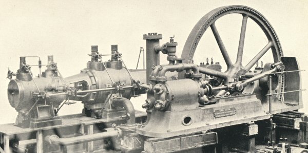
Paxman Tandem Compound Drop-Valve engine coupled to a Linde refrigeration compressor
(from Linde Mechanical Refrigeration by Hal Williams, published 1903.)
Catalogue Description of the Paxman Drop-Valve Engine
The description and specifications below are taken from a Paxman catalogue thought to have been issued in late 1913 or in 1914.
The drop-valve engine, with admission and exhaust valves of the double-beat type, actuated by trip-gear and eccentrics driven from a side shaft, superseded the old Corliss and similar engines in consequence of its greater economy, the higher rotary speeds possible by the trip valve gear, and the suitability of this engine for a higher degree of superheat than was permissible with the Corliss type.
Our own trip-gear engine is of very high-class design, adapted for high working pressures up to 140 lb. per square inch, and suitable for superheated steam. The bearing surfaces are large, and the whole design is of the most rigid and substantial construction.
Design. The single cylinder, coupled-compound and tandem-compound engines are shown on pages 26, 28 and 30. The frame of the engine is of the trunk girder type, capable of withstanding all the working strains of the engine. The illustration on page 32 shows a coupled-compound drop-valve engine mounted on a special girder frame to render the engine suitable for working upon a very bad foundation. This frame is charged for extra, and designed to suit each special condition.
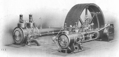
Drop-Valve Coupled Compound Engine
Cylinders. These are cast of a special mixture of iron, free from imperfections, fitted with a hard, close-grained, cast-iron liner, truly bored and machined. They are covered with non-conducting composition, and neatly lagged with planished blue sheet steel.
Crankshaft. Is of the best forged steel, turned all over, the outer end, beyond the flywheel, being carried by an outside bearing.
Valve Gear. The valve gear is of the "trip" variety. Both admission and exhaust valves are of the circular double-seated type, the steam admission valves being operated through trip levers and rods working from eccentrics on the side shaft. The exhaust valves are placed at the bottom of the cylinder which they drain. They are quietly opened and closed by suitable rollers and levers worked from the side shaft.
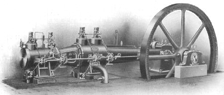
Drop-Valve Tandem Compound Engine
Lubrication. The high-pressure cylinder is provided with sight-feed lubricator, the crank-pin with centrifugal oiler, and all other working parts with drop-feed lubricators.
Governor. This is of our improved high-speed type, driven from the side shaft by suitable chain, and carried on a neat cast-iron stand. It is extremely sensitive, and capable of controlling the engine under varying conditions of load.
Flywheel. This is of suitable size for giving off the full power of the engine, carefully machined, and when necessary cast in halves. Teeth are cast in the rim for receiving the barring gear. If required, it can be grooved for driving ropes at an extra charge.
Handrails. Polished handrails are provided to guard the crank.
Fittings. The fittings supplied with these engines are of the highest class, and comprise : Stop valve, sight-feed lubricator to high pressure cylinder, drop-feed lubricators, cylinder drain cocks, complete set of spanners, oil feeder, and foundation bolts and plates.
Single Cylinder Engine Specifications
In the table below columns 9 and 10 show the diameters of steam and exhaust pipes respectively, columns 11 and 12 show the dimensions of flywheels turned for belt drive, columns 13 and 14 refer to flywheels grooved for rope drive showing the number and diameter of the rope grooves.
| Cylinder | Brake Horse-Power | Pipe dia. (inches) | Flywheel | Speed RPM | ||||||||||
|---|---|---|---|---|---|---|---|---|---|---|---|---|---|---|
| Dia. (ins.) | Stroke (ins.) | 80 lbs | 100 lbs | 120 lbs | Turned | Grooved | ||||||||
| Nor. Load | Max. Load | Nor. Load | Max. Load | Nor. Load | Max. Load | Stm | Exh | Dia | Face | No | Dia | |||
| 9 | 21 | 26 | 38 | 29 | 42 | 32 | 45 | 3 | 3½ | 8' | 7" | 3 | 1¼" | 135 |
| 10½ | 24 | 38 | 56 | 42 | 60 | 45 | 62 | 3½ | 4 | 9' | 9" | 3 | 1½" | 125 |
| 12 | 27 | 52 | 75 | 56 | 80 | 60 | 83 | 3½ | 4½ | 10' | 12" | 4 | 1½" | 115 |
| 14 | 30 | 72 | 100 | 77 | 110 | 82 | 115 | 4 | 5 | 10' | 15" | 5 | 1½" | 105 |
| 16 | 33 | 98 | 140 | 105 | 150 | 112 | 156 | 5 | 6 | 12' | 18" | 5 | 1¾" | 100 |
| 18 | 36 | 125 | 180 | 135 | 195 | 145 | 200 | 6 | 7 | 13' | 22" | 6 | 1¾" | 95 |
| 20 | 42 | 170 | 230 | 185 | 260 | 200 | 275 | 6 | 7 | 14' | 29" | 7 | 1¾" | 90 |
Coupled Compound and Tandem Compound Engines Specifications
The specifications given in the table below were common to both types. Columns 10 and 11 show the diameters of steam and exhaust pipes respectively, columns 12 and 13 show the dimensions of flywheels turned for belt drive, columns 14 and 15 refer to flywheels grooved for rope drive showing the number and diameter of the rope grooves.
| Cylinders | Brake Horse-Power | Pipe dia. (inches) | Flywheel | Speed RPM | |||||||||||
|---|---|---|---|---|---|---|---|---|---|---|---|---|---|---|---|
| Diameters (inches) | Stroke (ins.) | 100 lbs | 120 lbs | 140 lbs | Turned | Grooved | |||||||||
| Nor. Load | Max. Load | Nor. Load | Max. Load | Nor. Load | Max. Load | Stm | Exh | Dia | Face | No | Dia | ||||
| 9 | 15 | 21 | 63 | 76 | 68 | 84 | 73 | 90 | 3 | 5 | 8' | 11" | 5 | 1¼" | 135 |
| 10½ | 17 | 24 | 86 | 104 | 93 | 114 | 100 | 125 | 3½ | 5½ | 9' | 15" | 5 | 1½" | 125 |
| 12 | 20 | 27 | 124 | 150 | 133 | 162 | 140 | 180 | 3½ | 7 | 10' | 18" | 7 | 1½" | 115 |
| 14 | 23 | 30 | 165 | 200 | 180 | 220 | 190 | 240 | 4 | 8 | 10' | 23" | 8 | 1½" | 105 |
| 16 | 26 | 33 | 220 | 265 | 240 | 290 | 255 | 320 | 5 | 8½ | 12' | 26" | 8 | 1¾" | 100 |
| 18 | 30 | 36 | 305 | 365 | 330 | 400 | 350 | 440 | 6 | 10 | 13' | 33" | 10 | 1¾" | 95 |
| 20 | 34 | 42 | 435 | 520 | 470 | 570 | 500 | 620 | 6 | 12 | 14' | 42" | 13 | 1¾" | 90 |
Paxman Drop-Valve Engine Orders
Details of orders for 42 Paxman Drop-Valve engines, ordered between 1902 and 1925, are given in the table below. Information in this table is based on work of the late Graham Smart of Stourbridge, West Midlands, supplemented with details recorded in surviving Paxman copy order books. The listing is not claimed to be complete record of drop-valve orders.
Abbreviations used in the table below:
HTC = Horizontal Tandem Compound SC = Single Cylinder HCC = Horizontal Cross Compound
| Date Ordered | Order No | Engine No | Engine Details | Customer and Despatch Date |
|---|---|---|---|---|
| 02-04-02 | 6587 | 11368 11369 | Two HCC - 13" + 24" x 30" | Linde BR Co Ltd - for Gomshall Tannaries, Guildford, Surrey. Sent 03-04-02. |
| 18-06-02 | 6696 | 11501 | HTC - 17½" + 28" x 33", working pressure 100 psi. | Garton Hill & Co, Battersea - (with condenser). Sent 16-01-03. |
| 06-07-03 | 7091 | 11946 | HTC - 18" + 28½" x 33" | Dunlop Rubber Co, Birmingham. Sent 15-01-04. |
| 25-09-03 | 7158 | 12021 | Horizontal - 11½" + 20" x 27" (with No. II compressor, 5" + 8½" x 8") | Linde BR Co Ltd, for Scarborough. Sent 01-02-04. |
| 19-09-03 | 7162 | 12025 | HTC - 14" + 24½" x 30" | Linde BR Co Ltd, for West Hartlepool. |
| 05-10-03 | 7169 | 12033 | Horizontal - 11½" + 21½" x 27" | Linde BR Co Ltd, for Swansea. Sent 23-02-04. |
| 03-12-03 | 7213 | 12080A | 200HP Drop-Valve Engine, 14" + 24½" x 30" | Anglo Continental Co. Sent 09-11-04. |
| 14-01-04 | 7239 | 12109 | Horizontal - 16" + 24" x 18" | Linde BR Co Ltd, for Pendleton. Sent 21-05-04. |
| 14-09-04 | 7449 | 12350 12351 | Two HTC - 11½" + 20" x 27" | Linde BR Co Ltd, for Melbourne, Australia. Sent 21-12-04. |
| 09-01-05 | 7557 | 14008 | 50HP SC Drop-Valve Engine, 10" x 24" | Moonens & Gaucet (of Brussels, Belgian Agents) for Liege exhibition - sold to Agent under O/No 8066 of July 1906. |
| 01-04-05 | 7628 | HTC - 16" + 27" x 33" | Linde BR Co Ltd, for Riga, Russia (now Latvia). Sent 21-06-05. | |
| 02-04-05 | 7646 | HTC - 12" + 20" x 27" (with No. IV compressor) | Linde BR Co Ltd, for Sydney Australia. Sent 01-07-05. | |
| 23-05-05 | 7680 | Compound Drop-Valve Engine, 14" + 24½" x 30" (with No. VI compressor) | Linde BR Co Ltd, for Union Cold Storage Co. Sent 03-07-05 | |
| 23-05-05 | 7681 | Compound Drop-Valve Engine, 12" + 20" x 27" (with No. VI compressor) | Linde BR Co Ltd, for Union Cold Storage Co. Sent 03-07-05 | |
| 22-02-06 | 7892 | SC Drop-Valve 18" x 33" (with No. VI compressor, 13" x 29") | Linde BR Co Ltd, for Melbourne, Australia. Sent 28-05-06. | |
| 08-03-07 | 8405 | 14368 | HTC - 10½" + 18½" x 24" | Hassabo Mohamed & Co (Paxman's Agent in Egypt), Alexandria, Egypt. Sent 21-08-07. |
| 21-06-07 | 8499 | 14466 | HCC - 16" + 26" x 33" | Mitsui & Co, Kobe, Japan. Sent 13-03-08. |
| 20-09-07 | 8552 | 14527 | HCC - 13½" + 21½" x 27" | Jacob Walker & Co, Rio de Janiero, Brazil. Sent 03-03-08. |
| 18-10-07 | 8603 | 14583 | SC Drop-Valve Engine - 12" x 24" (with No. V compressor) | Linde BR Co Ltd, for Sydney, Australia. Sent 07-01-08. |
| 04-12-07 | 8629 | 14617 | HTC - 11½" + 21½" x 27" | Linde BR Co Ltd, for Swansea. Sent 13-04-08. |
| 30-03-08 | 8743 | HTC - 16" + 26" x 33" | Dunlop Rubber Co, Osaka, Japan. Note: Written in pencil in the 'Date Sent' column of the copy order book is 'In abeyance'. As the 'Engine No' column is also blank, it seems likely the engine was not built. | |
| 16-04-08 | 8755 | 14744 | SC Drop-Valve Engine - 18" x 33" (with compressor) | Linde BR Co Ltd, for Melbourne, Australia. Sent 31-07-08. |
| 20-08-08 | 8892 | HTC - 14" + 24½" x 30" | Linde BR Co Ltd, for Russia. Sent 15-12-08. | |
| 20-08-08 | 8893 | HTC - 12" + 20" x 27" | Linde BR Co Ltd, for Russia. Sent 03-12-08. | |
| 24-11-09 | 9272 | 15300 | HTC - 14" + 23" x 30" | Jeremiah Lyon & Co, Malacca. Sent 12-04-10. |
| 09-03-10 | 9377 | 15407 | HTC - 18½" + 38½" x 36" | Mitsui & Co Ltd, Kobe, Japan. Sent 29-11-10. |
| 12-04-10 | 9411 | 15440 | HCC - 12" + 20" x 27" | Bell Graphite Co, Montreal, Canada. Sent 28-07-10. |
| 20-01-11 | 10830 | HTC - 14" + 23" x 30" | Lidgerwood WVV, for Dutch Indies. | |
| 28-04-11 | 11019 | 17047 | HCC - 16" + 25½" x 21" (with No. Va compressor, 10" x 21") | Linde BR Co Ltd, for Australia. Sent 02-09-11. |
| 13-10-11 | 11257 | 17286 | HTC - 10" + 17" x 24" (with No. V compressor) | Linde BR Co Ltd. Sent 20-02-12 |
| 13-10-11 | 11258 | 17287 | HTC - 10" + 17" x 24" | Linde BR Co Ltd. Sent 22-02-12 |
| 31-07-15 | 13081 | 19111 | Compound Drop-Valve Engine - 11½" + 20" x 27" (with compressor, 13" x 23") | Wildridge & Sinclair, Australia. Engine sent 11-09-16, compressor on 17-07-16. |
| 25-11-15 | 13153 | 19183 | HTC - 13" + 23" x 30" (with No. VI DA SD compressor, 13" x 23", O/No 13154, Reg. No 19184) | Wildridge & Sinclair, Australia. Engine and compressor sent 23-11-16. |
| 18-05-17 | 13598 | 19628 | SC Drop-Valve Engine - 12" x 24" (with No. IVa Ammonia compressor, 8½" x 15", O/No 13599, Reg. No 19629) | Lightfoot Refrigeration Co, for Robert Graesser Ltd. Sent 09-07-18 |
| 28-08-19 | 14052 | 20082 | HTC - 14" + 23" x 30" (with No. VI SD compressor, 13" x 23", O/No 14053) | Lightfoot Refrigeration Co, for India. Sent 05-01-21. |
| 28-08-19 | 14054 | 20084 | HTC - 14" + 23" x 30" (with No. VI SD compressor, 13" x 23", O/No 14055) | Lightfoot Refrigeration Co, for India. Sent 19-01-21. |
| 28-08-19 | 14056 | 20086 | HTC - 14" + 23" x 30" (with No. VI SD compressor, 13" x 23", O/No 14057) | Lightfoot Refrigeration Co, for India. Sent 01-02-21. |
| 28-08-19 | 14058 | 20088 | HTC - 14" + 23" x 30" (with No. VI SD compressor, 13" x 23", O/No 14059) | Lightfoot Refrigeration Co, for India. Sent 10-02-21. |
| 15-11-21 | 14737 | 20767 | HTC - no dimensions given (with Ammonia compressor, 15" x 24", O/No 14738, Reg. No 20768) | Lightfoot Refrigeration Co, for Milford Haven. Sent 05-07-22. |
| 18-04-25 | 15733 | 21763 | SC Drop-Valve Engine - 20" x 30" | Borneo Co Ltd, Bangkok. Sent 25-08-25. |
42 engines in total. 26 of these were for the Linde British Refrigeration Company or its successor, the Lightfoot Refrigeration Company, coupled to ammonia refrigeration compressors. For more on Paxman steam engines and Linde/Lightfoot compressors see the page Paxman and Refrigeration Compressors.
Page updated: 19 JAN 2014